9
The Delay, Reverb and Chorus effects have further parameters available for adjustment
via the FX Menu; these are described in detail later in the User Guide. Summit also has a
dedicated four-slot FX Modulation Matrix with its own menu: this allows a wide range of FX
parameters to be modulated by various synth sources.
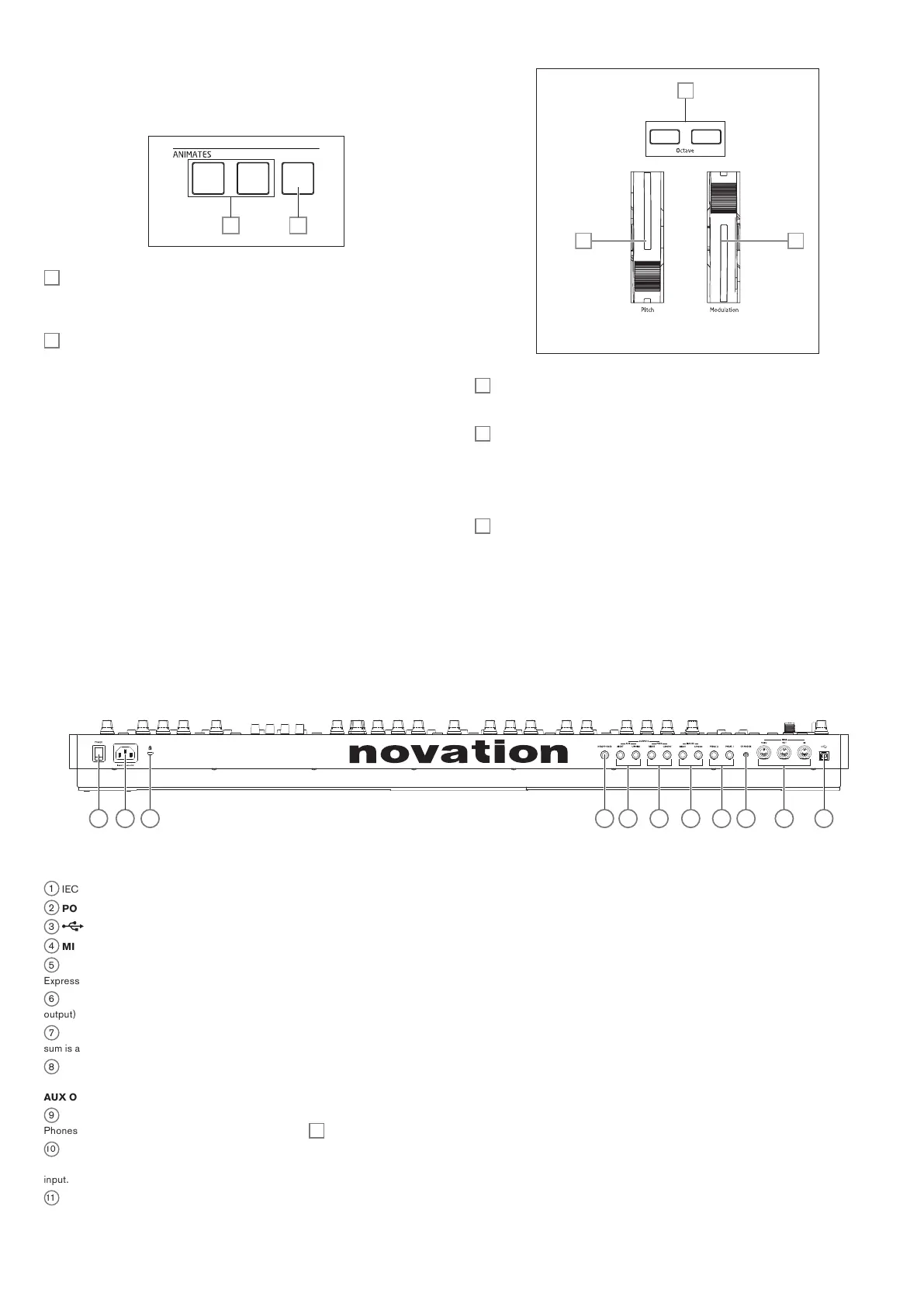
ANIMATE :
80 81
80
ANIMATES 1 and 2 – add an “instant” effect to the sound currently being generated
by activating additional, pre-programmed modulation and effects routings that have been
set up in the modulation matrix. These buttons are great in live performance: most of
Summit’s factory Patches include Animate functions.
81
Hold – pressing Hold will “lock” the Animate function in an “On” state. You can either
press Hold before pressing ANIMATE, or vice-versa. Pressing ANIMATE a second time
releases both the Animate and Hold functions.
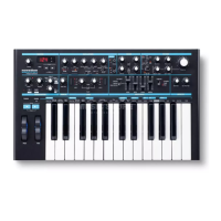
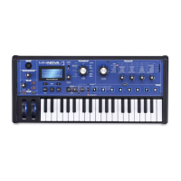
PERFORMANCE CONTROLS:
82 83
84
82
Soft rubber Pitch wheel with a positive return to the centre position. The default range
is +/- one octave, but the Bend Range parameter in the Oscillator Menu allows a range of
up to +/- two octaves for each oscillator independently.
83
Soft rubber Modulation wheel, the specific effect of which will vary with Patch. It may
also be assigned as a Modulation Matrix source, to modify one or more parameters.
Note that the Pitch and Modulation wheels have internal illumination, colour-coded to follow
the current A/B MULTIPART selection [12].
84
Octave + and Octave – buttons – shift the keyboard up or down by an octave with
each press: the maximum range is +/-3 octaves. The illumination of the buttons increases
with the degree of shift; both buttons are dark when no octave shift is in effect.
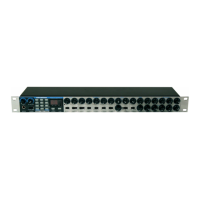
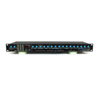
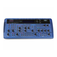
Rear Panel
1
2
3
6
9
4
5
7
10
10
8
1
IEC mains inlet – connect the supplied AC cable here.
2
POWER – mains on/off switch.
3
standard Type ‘B’ USB 2.0 port. Connect to a Type A USB port on a computer using the supplied cable. Note that the USB port only carries MIDI data, not audio.
4
MIDI IN, OUT and THRU – standard 5-pin DIN MIDI sockets for connecting Summit to a keyboard or other MIDI-equipped hardware.
5
PEDAL 1 and PEDAL 2 – two 3-pole (TRS) ¼” jack sockets for connection of switch (e.g., sustain) and/or expression pedals. The sockets detect switch pedal polarity automatically.
Expression pedals are also detected automatically and can be routed directly as sources available to the Modulation Matrix. Switch pedal functions are configured in the Settings menu.
6
CV MOD IN – 3.5 mm jack socket for connecting an external Control Voltage source in the range of +/-5 V. This permits other analogue instruments (equipped with a compatible CV
output) to modulate Summit’s sounds.
7
MAIN OUTPUTS – two ¼” 3-pole (TRS) jack sockets carrying Summit’s main output signal. Use both L/MONO and RIGHT for full stereo: if RIGHT is unconnected, a mono (L+R)
sum is available at L/MONO. Outputs are pseudo-balanced.
8
AUX OUTPUTS – Summit is equipped with a second stereo output; Parts A and B can be independently assigned to either output, which is a powerful feature when using Multi
Patches. It is also possible to assign the (wet) outputs of the FX section for either Part A and B to the main or auxiliary outputs. The mono/stereo options of the
AUX OUTPUTS are identical to those of the MAIN OUTPUTS.
9
HEADPHONES – 3-pole (TRS) ¼” jack socket for stereo headphones.
Phones volume is adjusted by the Master Volume control
1
.
10
INPUTS – two ¼” 3-pole (TRS) jack sockets for applying signals to Summit’s FX processors from external sources. A menu option (Voice Menu Page 3) allows a choice of inserting
the external signal into the processing chain either pre or post the filter section. Use both L/MONO and RIGHT for full stereo: if RIGHT is unconnected, the signal will be treated as a mono
input.
11
Kensington Security Slot – to secure your synth.