6
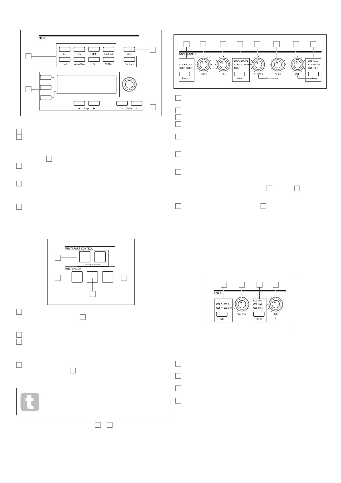
MENU:
8
11
9
10
8
20 character x 4 row OLED display. Displays one of the menus selected by the buttons
9
, or the current Patch details. Pages within each menu may be selected with the
Page I and Page H buttons below the display. Adjusting any of Summit’s rotary controls
(except MASTER) invokes an alternative display showing the value of the parameter being
adjusted until the control is released. The three buttons to the left of the display assign the
parameter control
10
to a particular row of the page being displayed.
9
Nine buttons selecting the menu to be displayed: Osc, Env, LFO, Arp/Clock, Mod,
Voice, FX, FX Mod and Settings. These buttons are all “toggles”: press them a second
time to exit the menu; the display will revert to the Patch information page.
10
Parameter adjustment may either be made rapidly by the rotary control or incremented/
decremented one parameter value at a time with the Value + / Value - buttons. These controls
can also be used to scroll through the Patch library (Single or Multi, as currently active) if the
display is currently showing Patch data and Row 2 (‘Patch’) is selected.
11
Save – opens the first of three menu pages, which enable the current synth settings to be
saved as a User Patch in memory.
MULTIPART and MULTIMODE CONTROL :
13
12
15
10
12
The A and B buttons select which Part – A or B - of a Multi Patch is assigned to the
synth controls, and in Dual mode (see
15
below), which Part you hear. A and B may be
pressed together to select Both mode, when the synth controls will affect both Parts
simultaneously.
13
Layer - in Layer mode, the keyboard plays both Parts A and B of a Multi Patch.
14
Split – this mode lets you play Part A with the left hand and Part B with the right. The
“split point” is, by default, middle C (C3). The split point can be redefined by pressing and
holding Split while pressing the appropriate key on the keyboard; the new split point will
be saved with the Patch.
15
Dual – in this mode, the whole keyboard is assigned to either Part A or Part B,
selected by the A and B buttons
12
. Both Parts may be selected by pressing A and B
together; in this case, the result is the same as selecting Layer mode. In this mode, you can
control the parameters of both Parts of a Multi Patch simultaneously.
You can use Dual mode to just play one of the two Parts if you need to use
the FX section for the other Part to process an external signal instead.
NOTE: In Multi Patch Mode, the above buttons
12
to
15
are internally illuminated: the
colour reflects the Part currently assigned to Summit’s synth controls. Part A is indicated
by blue, Part B by orange and the A+B Both mode by white.
OSCILLATORS:
The three Oscillators have identical sets of controls.
16 19 2317 18 20 21 22
16
Range – steps through the oscillator’s base pitch ranges. For standard concert pitch
(A3 = 440 Hz), set to 8’.
17
Coarse – adjusts the pitch of the selected oscillator over a range of ±1 octave.
18
Fine – adjusts the oscillator pitch over a range of ±100 cents (±1 semitone).
19
Wave – steps through the range of available oscillator waveforms – sine, triangular,
sawtooth, pulse and more (the menu offers an extensive set of additional wavetables for more).
20
Mod Env 2 Depth – controls the amount by which the oscillator pitch changes as a
result of modulation by Envelope 2. All Modulation Depth controls are “centre-zero” and
thus positive values will increase the pitch and negative values will decrease the pitch.
21
LFO 2 Depth – controls the amount by which the oscillator pitch changes as a
result of modulation by LFO 2. Pitch changes are bi-polar (up and down); uni-polar pitch
modulation is available by the use of the Modulation Matrix.
22
Shape Amount – controls further modifications of the waveform shape, and is active
for all wave shapes. With pulse waves, it adjusts the pulse width; with sine, triangle and
sawtooth waves it produces wavefolding, which imparts additional harmonics to the basic
waveform. When more is selected by the Wave switch
19
and Source
23
is set to
Manual, the control navigates continuously through the five waveforms of the wavetable
currently selected for the WaveMore parameter in the Oscillator menu.
23
Source – assigns the Shape Amount control
22
to one of three sources
which further alter the waveform shape. The options are: modulation by Envelope 1
(Mod Env 1), modulation by LFO 1 (LFO 1), and Manual, when the Shape Amount
control itself modifies the wave shape. The three sources are additive: all may be used
simultaneously.
All three oscillators have further parameters available for adjustment via the Osc Menu.
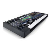
LFO 1 & LFO 2:
The two LFOs have identical sets of controls.
24 2625 27
The outputs of either LFO may be used to modulate numerous other synth parameters.
Summit’s LFOs are all per-voice; that is, the modulating effect of the LFO waveform is
applied independently to each of the eight voices making up the output of each oscillator.
24
Type – steps through the available waveforms: triangle, sawtooth, square, sample and
hold. The associated LEDs give a visual indication of the LFO speed and waveform.
25
Fade Time – sets the timing of the LFO’s action: it is possible to “ramp” the LFO up or
down or to delay its effect. The options are set in the LFO menu.
26
Range – selects High or Low; the third option is Sync, which synchronises the LFO
frequency to the internal arp clock or to an external MIDI clock if one is present.
27
Rate – sets LFO frequency.
Both LFOs have further parameters available for adjustment via the LFO Menu: these are
described in detail later in the User Guide.