- 17 -
MOUNTING INSTALLATION
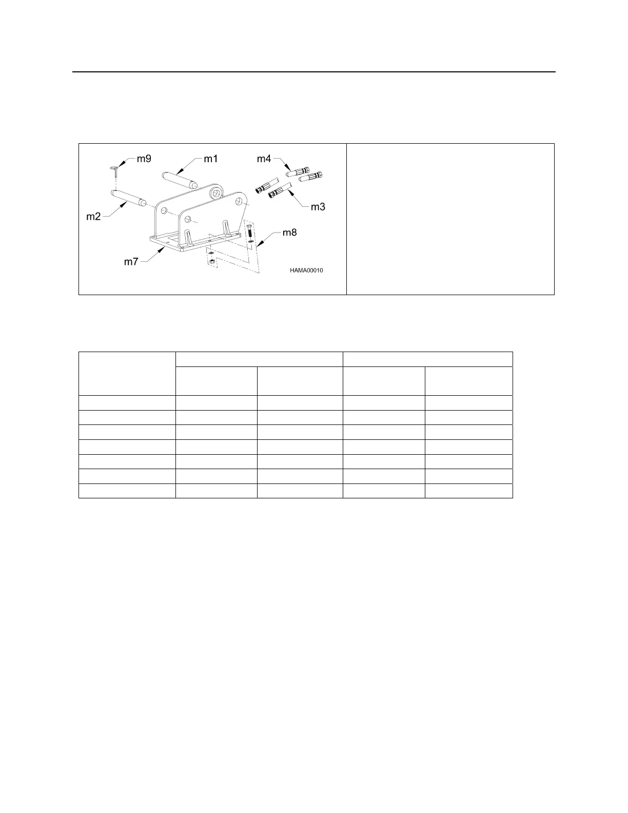
NPK Mounting Installation Kits include the parts required to adapt the NPK HYDRAULIC
HAMMER to the carrier. NPK mounting kits include the hammer mounting bracket, flow
control valve (if required), and hoses to connect to the carrier hydraulic system.
m1 Stick Pin (If Required)
m2 Link Pin (If Required)
m3 (Whip) Pressure Hose
m4 (Whip) Return Hose
m7 Top Bracket
m8 Hammer Bolt Package
m9 Klik Pin
*TORQUES OF ALL BOLTS SHOWN ARE WITH THREADS BEING LUBRICATED
WITH ANTI-SEIZE COMPOUND.
HAMMER BRACKET ADAPTER BRACKET
MODEL
BOLT
DIA
TORQUE
ft/lb (Nm)
BOLT
DIA
TORQUE
ft/lb (Nm)
GH06 1” 500 (678) 5/8” 165 (225)
GH07 1” 500 (678) 5/8” 165 (225)
GH1 1” 500 (678) 5/8” 165 (225)
GH2/GHS2 1” 500 (678) 5/8” 165 (225)
GH3 1-1/4” 1000 (1356) 5/8” 165 (225)
GH4 1-1/2” 1250 (1695) 5/8” 165 (225)
GH6 1-1/2” 1250 (1695) 1” 550 (745)
*Refer to NPK Installation Kit Manual for additional information.