62 | nVent.com
Measurement Range nominal load, repeatability: ± 10% of reading
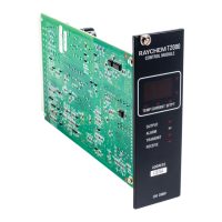
A7 – CM 2000+ Control Module Specifications
Operating Ambient –40 to 149°F (–40 to 65°C)
Control Modes Proportional, Deadband, Proportional Ambient SSR,
Proportional Ambient Contactor modes, adjustable 2 to 90°F
(1 to 50°C)
Control Output +12 VDC nominal, 50 mA Max.
Sensor Inputs Two(2) 3-wire 100 ohm Platinum RTDs (DIN 43760,
a=0.00385W/W/°C) open/shorted sensor detection/protection,
lead resistance compensation up to 20W per lead max.
Power Requirements 120 to 240 VAC nominal, 50 ± 2 Hz or 60 Hz ± 3 Hz, 1 Ph, 5W Max.
Temperature –76 to 1058°F (–60 to 570°C), accuracy: ± 0.5% of span ± 1 LSD
Measurement Range
Voltage 80 to 295 VAC, 50/60 Hz, accuracy: ±1% of span ± 2 LSD,
Measurement Range repeatability: ± 1.5% of span
Current 0.3 to 100 A, accuracy: ± 2.5% of reading ± resolution where
Measurement Range resolution = 0.1 A (0.3 to 11 A range), 0.3 A (11 to 40 A range),
0.7 A (40 to 100 A range) repeatability: ± 3% of reading ± resolution
Ground Fault 20 to 100 mA, accuracy: ± 2.5% of span ± 2 LSD at
Measurement Range nominal load, repeatability: ± 4% of span
A8 – AC 2000 Alarm/Communications interface Card Specifications
Operating Ambient –40 to 149°F (–40 to 65°C)
Alarm Output SPDT Hermetically sealed relay, 240 VAC @ 0.5 A Max.
“Alarm” status LED
Communications ModifiedBell103FSK,300baud2-wirehalf-duplex
communications, isolated to 250 VAC, transient/open/short
circuit protected
“Receive” , “Carrier”, “Transmit”, and “Req To Send” status LEDs
Control Module CM 2000 or CM 2000+ Control Modules:
Communications 40 Controllers max. @300 baud
Power Requirements 90 - 240 VAC, 60 Hz, 1Ph
Power Consumption < 5 watts typical
A9 – AC 2000+ Alarm/Communications Interface Card Specifications
(Specifications @ 25°C and rated voltage unless otherwise noted and subject to change
without notice)
Operating Ambient –40 to 149°F (–40 to 65°C)
Approvals CSA (C/US) Certified & FM Approved
Classification Class I, Division 2, Groups A,B,C,D
T-code: T4A and Ordinary Locations
Output Devices Individual N.C. Alarm and Warning relay drive outputs
+12 VDC @ 100 mA Max.
“Alarms” and “Warnings” status LEDs
Communications Local Port : RS-485 mode
• Non-Isolated, 2-wire, 32 devices Max.
• 300 to 9600 baud
• Modbus RTU/ASCII protocols, selectable paged (GCC/780
compatibleorlinearmapping
• “Receive” and “Transmit” status LEDs
Local Port: RS-232C mode
• DE9S connector, DCE pinout
• 300 to 9600 baud
• Modbus RTU/ASCII protocols, selectable paged (GCC/780
compatible) or linear mapping

 Loading...