Platform Adaptation and Bring-Up
Jetson Nano Platform Adaptation and Bring-Up Guide DA_09361-002 | 19
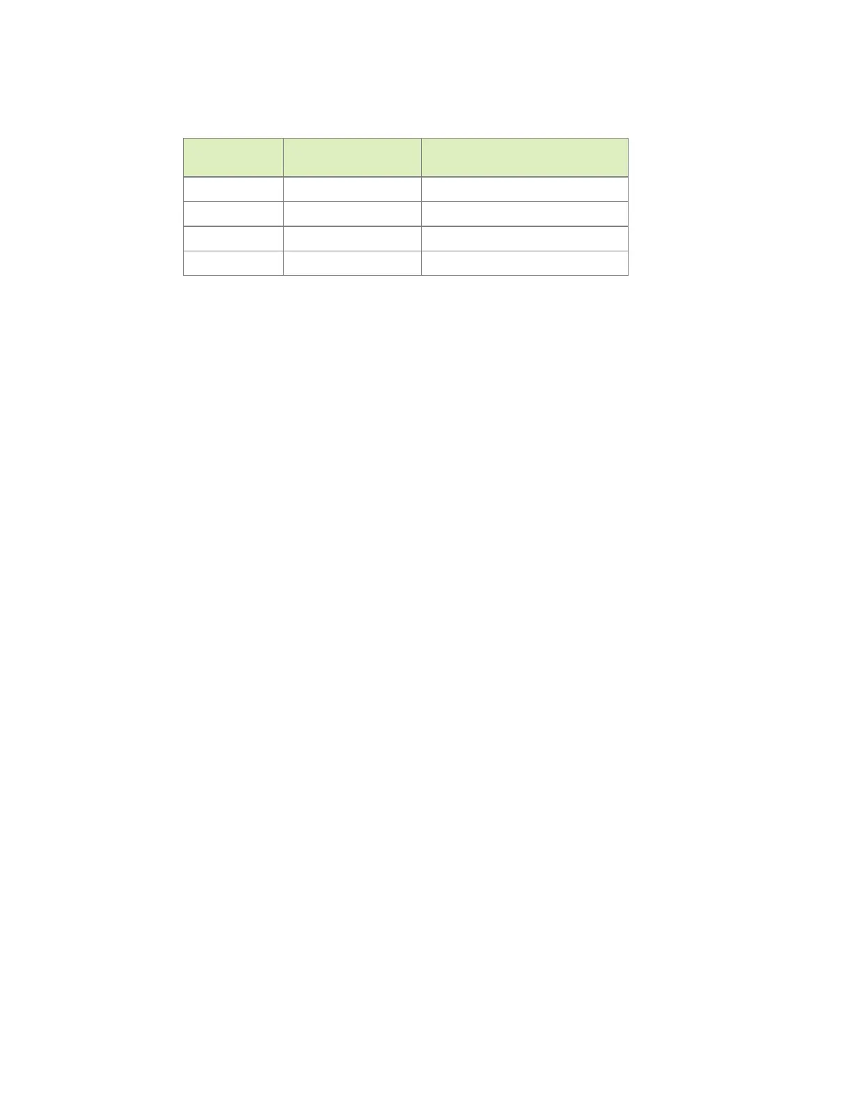
Table 3. GPIO states and corresponding output cable states
GPIO_PZ1
(ID)
GPIO_PCC4
(VBUS_DETECT) EXTCON_STATE
1 1 0x0 (EXCON_NONE)
0 0 0x2 (EXTCON_USB_HOST)
0 1 0x2 (EXTCON_USB_HOST)
1 0 0x1 (EXTCON_USB)
Under the extcon Node
Port switching between the roles of an OTG port is defined by the state of the ID pin and
the VBUS_DETECT pin and the settings of the external connector class.
Create an extcon device node and property list using the properties listed below and
the table of GPIO states and cable states (Figure 2).
• compatible
Value must be extcon-gpio-states.
• extcon-gpio,name
Name of the extcon device.
• gpios
List of the GPIOs.
• extcon-gpio,irq-flags
IRQ flags for GPIO.
• extcon-gpio,debounce
Debounce time in milliseconds.
• extcon-gpio,wait-for-gpio-scan
Wait timeout in milliseconds for scanning all GPIOs’ states after a GPIO state change
is detected and debounce time has passed.
• extcon-gpio,out-cable-names
Output cable names.
• extcon-gpio,cable-states
GPIO states and their corresponding output cable states. The value is an array of
byte values. Each even-numbered byte is a GPIO state, and the following odd-
numbered byte is the corresponding output cable state.
• cable-connected-on-boot

 Loading...


