NVIDIA Jetson TX2/TX2i OEM Product Design Guide
JETSON TX2/TX2i OEM PRODUCT | DESIGN GUIDE | 20180618 22
Signal Routing Conventions
Throughout this document, the following signal routing conventions are used:
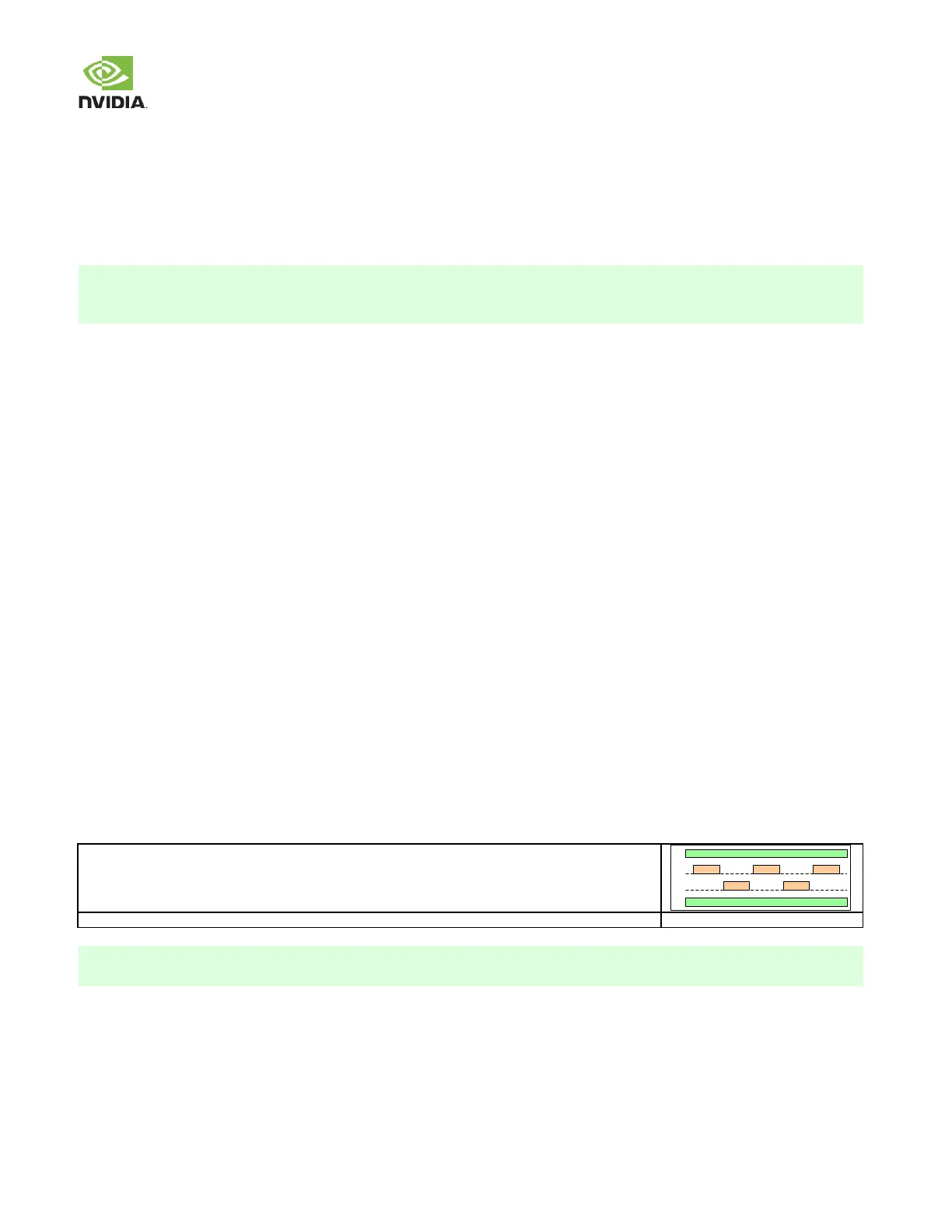
SE Impedance (/ Diff Impedance) at x Dielectric Height Spacing
▪ Single-ended (SE) impedance of trace (along w ith differential impedance for diff pairs) is achieved by spacing
requirement. Spacing is multiple of dielectric height. Dielectric height is typically different for microstrip & stripline.
Note: 1 mil = 1/1000th of an inch.
General Routing Guidelines
Pay close attention w hen routing high speed interfaces, such as HDMI/DP, USB 3.0, PCIe or DSI/CSI. Each of these interfaces
has strict routing rules for the trace impedance, width, spacing, total delay, and delay/flight time matching. The following
guidelines provide an overview of the routing guidelines and notations used in this document.
▪ Controlled Impedance
Each interface has different trace impedance requirements & spacing to other traces. It is up to designer to
calculate trace w idth & spacing required to achieve specified single-ended (SE) & differential (Diff) impedances.
Unless otherw ise noted, trace impedance values are ±15%.
▪ Max Trace Lengths/Delays
Trace lengths/delays should include main PCB routing and any additional routing on a Flex/ secondary PCB
segment connected to main PCB. The max length/delay should be from the module to the actual connector (i.e.
USB, HDMI, SD Card, etc.) or device (i.e. onboard USB device, Display driver IC, camera imager IC, etc.)
▪ Trace Delay/Flight Time Matching
Signal flight time is the time it takes for a signal to propagate from one end (driver) to other end (receiver). One
w ay to get same flight time for signal w ithin signal group is to match trace lengths w ithin specified delay in the
signal group.
- Total trace delay = Carrier PCB trace delay only. Do not exceed maximum trace delay specified.
- For six layers or more, it is recommended to match trace delays based on flight time of signals. For example,
outer-layer signal velocity could be 150psi (ps/inch) & inner-layer 180psi. If one signal is routed 10 inches on
outer layer & second signal is routed 10 inches in inner layer, difference in flight time between tw o signals w ill
be 300ps! That is a big difference if required matching is 15ps (trace delay matching). To fix this, inner trace
needs to be 1.7 inches shorter or outer trace needs to be 2 inches longer.
- In this design guide, terms such as intra-pair & inter-pair are used w hen describing differential pair delay.
Intra-pair refers to matching traces w ithin differential pair (for example, true to complement trace matching).
Inter-pair matching refers to matching differential pairs average delays to other differential pairs average
delays.
General PCB Routing Guidelines