NVIDIA Jetson TX2/TX2i OEM Product Design Guide
JETSON TX2/TX2i OEM PRODUCT | DESIGN GUIDE | 20180618 33
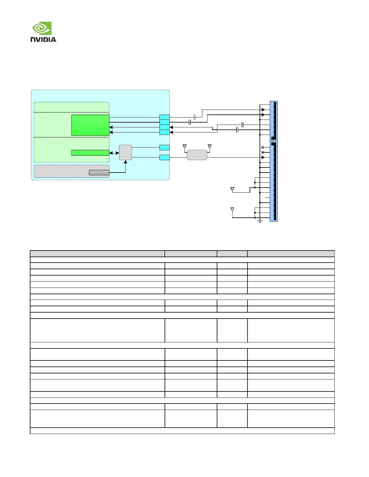
5.3 SATA
A Gen 2 SATA controller is implemented on Jetson TX2/TX2i. The interface is brought to the module connector as show n in the
figure below .
Figure 18. SATA Connection Example
Tegra
PEX_TX5P
PEX_TX5N
PEX_RX5P
PEX_RX5N
PEX, USB
3.0 & SATA
SATA_TX+
SATA_TX
SATA_RX+
SATA_RX
PEX1_CLKREQ#
SATA_DEV_SLP
D45
D46
G45
G46
1
2
3
4
5
6
7
8
9
10
11
12
13
14
15
16
17
18
19
20
21
22
D47
PEX_L2_CLKREQ_N
Level
Shifter
VDD_1V8 VDD_3V3_SLP
PEXCTL
Mux
C47
PMIC
GPIO7
SEL
VDD_12V_SLP
VDD_5V0_IO_SLP
0.01uF
0.01uF
0.01uF
0.01uF
Jetson TX2/TX2i
SATA Design Guidelines
Table 26. SATA Signal Routing Requirements
Max Frequency Bit Rate / UI
Unidirectional, differential
Configuration / Device Organization
Trace Impedance Differential Pair / Single Ended
Trace Spacing
Pair-to-pair (inter-pair) Stripline / Microstrip
To plane & capacitor pad Stripline / Microstrip
To unrelated high-speed signals Stripline / Microstrip
Breakout region Max Length
Spacing
4x or wider dielectric height spacing is
preferred
Max PCB Via distance from pin
Max Within Pair (Intra-Pair) Skew
Intra-pair matching between subsequent discontinuities
Do trace length matching before hitting
discontinuities
Differential pair uncoupled length
AC Cap Value typical (max)
AC Cap Location (max distance from adjacent discontinuities)
The AC cap location should be located as
close as possible to nearby
discontinuities.