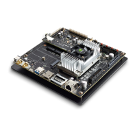
NVIDIA Jetson TX2/TX2i OEM Product Design Guide
JETSON TX2/TX2i OEM PRODUCT | DESIGN GUIDE | 20180618 9
3.0 POWER
Jetson TX2/TX2i is not hot-pluggable. Before installing or removing the module, the main power
supply (to VDD_IN pins) must be disconnected and adequate time (recommended > 1 minute) must
be allowed for the various power rails to fully discharge.
Table 5. Jetson TX2/TX2i Power & System Pin Descriptions
Usage on the
Carrier Board
Main power Supplies PMIC & external supplies
5.5V-19.6V (TX2)
9.0V 19.0V (TX2i)
(See note 1)
Carrier Power On. Used as part of the power up sequence.
The module asserts this signal when it is safe for the carrier
board to power up. -up to VDD_3V3_SYS is
present on the module.
Carrier Board Standby: The module drives this signal low
when it is in the standby power state.
Charger Present. Connected on module to PMIC ACOK
through FET & -up
internally to MBATT (VDD_5V0_SYS). Can optionally be used
to support auto-power-on where the module platform will
power-on when the main power source is connected instead
of waiting for a power button press.
MBATT level 5.0V
(see note 2)
Power Button. Used to initiate a system power-on.
-up to
VDD_5V0_SYS. Also connected to Tegra POWER_ON pin
-up to VDD_1V8_AP near
Tegra.
Reset In. System Reset driven from PMIC to carrier board for
devices requiring full system reset. Also driven from carrier
board to initiate full system reset (i.e. RESET button). A pull-
up is present on module.
Reset Out. Reset from PMIC (through diodes) to Tegra &
eMMC reset pins. Driven from carrier board to force reset of
Tegra & eMMC (not PMIC). An external 100pull-up to
1.8V near Tegra (module pin side) & external
pull-up to 1.8V on the other side of a diode (PMIC
side).
Sleep Request to the module from the carrier board. An
internal Tegra pull-up is present on the signal.
VDD_IN Power Bad. Carrier board indication to the module
that the VDD_IN power is not valid. Carrier board should de-
assert this (drive high) only when VDD_IN has reached its
required voltage level and is stable. This prevents Tegra from
powering up until the VDD_IN power is stable.
Real-Time-Clock. Optionally used to provide back-up power
for RTC. Connects to Lithium Cell or super capacitor on
Carrier Board. PMIC is supply when charging cap or coin cell.
Super cap or coin cell is source when system is disconnected
from power.
Battery Back-up
using Super-
capacitor
Battery Over-current (& Thermal) warning
Power button & SC7 wake interrupt
Module power configuration identification. Tied to GND on
Jetson TX2i. Floating on Jetson TX2. Determines the power-
on mechanism used to support both Jetson TX2 & TX2i.
Module power
configuration ID

 Loading...