NVIDIA Jetson TX2/TX2i OEM Product Design Guide
JETSON TX2/TX2i OEM PRODUCT | DESIGN GUIDE | 20180618 86
16.0 APPENDIX A: GENERAL LAYOUT GUIDELINES
16.1 Overview
Trace and via characteristics play an important role in signal integrity and pow er distribution on the module. Vias can have a
strong impact on pow er distribution and signal noise, so careful planning must take place to ensure designs meet NVIDIA’s via
requirements. Trace length and impedance determine signal propagation time and reflections, both of w hich can greatly improve
or reduce the performance of the module. Trace and via requirements for each signal type can be found in the corresponding
chapter; this appendix provides general guidelines for via and trace placement.
16.2 Via Guidelines
The number of vias in the path of a given signal, pow er supply line, or ground line can greatly affect the performance of the
trace. Via placement can make differences in current carrying capability, signal integrity (due to reflections and attenuation), and
noise generation, all of w hich can impact the overall performance of the trace. The follow ing guidelines provide basic advice for
proper use of vias.
16.2.1 Via Count and Trace Width
As a general rule, each ampere of current requires at least tw o micro-vias.
16.2.2 Via Placement
If vias are not placed carefully, they can severely degrade the robustness of a board’s pow er plane. In standard deigns that don’t
use blind or buried vias, construction of a via entails drilling a hole that cuts into the pow er and ground planes. Thus, incorrect
via placement affects the amount of copper available to carry current to the power balls of the IC.
16.2.3 Via Placement and Power/Ground Corridors
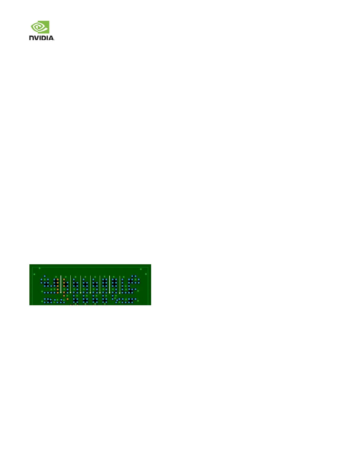
Vias should be placed so that sufficiently w ide pow er corridors are created for good power distribution, as show in Figure 47.
Figure 47. Via Placement for Good Power Distribution
Care should also be taken to avoid use of “thermal spokes” (also referred to as “thermal relief”) on pow er and ground vias.
Thermal spokes are not necessary for surface-mount components, and the narrow spoke w idths contribute to increased
inductance. The metal on the inner layers betw een vias may not be flooded w ith copper if sufficient spacing is not provided. The
diminished spacing creates a blockage and forces the current to find another path due to lack of copper, as show n in Figure 48
and Figure 49. This leads to power delivery issues and impedance discontinuities w hen traces are routed over these plane
voids.