Table 1. Connectors, LEDs, buttons and headers (continued)
Circuit ref (Rev E) Description Default Reference
SPI and I
2
C ports of the i.MX RT685
that are also designated for ISP
boot. This connector can be used to
work with a remote host, or as an
interface to off-the-shelf PMod
expansion boards.
J47 Flexcomm interface. N/A Flexcomm header
P1 Electret mic. N/A Schematic
SW1, SW2
User buttons. These buttons, when
pressed, pulls the connected i.MX
RT685 pin (P1_1 for SW1 and P0_10
for SW2) to ground. A 100 K ohm
pull up to VDDIO_1 is connected to
the pin.
N/A User buttons (SW1 and SW2)
SW3
Reset button. When pressed, reset
is applied to the i.MX RT685,
TFA9894 amplifiers, Octal SPI flash,
pSRAM, expansion connector
(Arduino reset, if JP14 is installed).
N/A Reset
SW4 PMIC on button. N/A PMIC-ON
SW5
Boot Config switch. ISP boot mode
selection. Switch the DIP switch for
ISP port signal to ON to pull that pin
low via a 1K ohm resistor. Switch 1
is for ISP0, 2 for ISP1 and 3 for
ISP2.
ISP0 ON
ISP1 OFF
ISP2 ON
ISP boot config
U1 LPC4322. N/A Schematic
U6 Accelerometer FXOS8700CQ. N/A Accelerometer
U8 Audio CODEC. N/A Audio Codec
U12, U17 Digital Audio Amplifiers N/A Audio digital amplifiers
U18 MIMXRT685. N/A Schematic
U19 Octal SPI Flash. N/A Schematic
U20
PMIC. Programmable output voltage
regulator with four different outputs:
SW1, SW2, LDO1 and LDO2.
N/A PMIC (PCA9420)
U40, U41 On-Board DMICs. N/A On-board DMIC
U108 pSRAM N/A Schematic
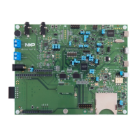
Figure 3 shows location of jumpers and headers.
NXP Semiconductors
Board layout and settings
i.MX RT685 Evaluation Board, Rev. 0, March 20 2020
User's Guide 7 / 31
 Loading...


