6.1 Debug connector pinouts
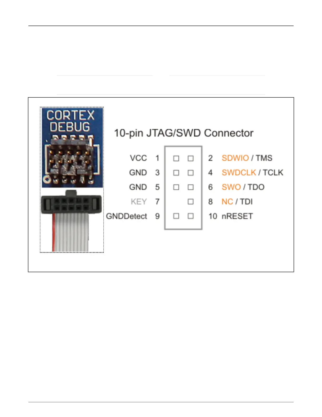
As the LPC55Sxx’s JTAG only for BSDL scan, you can use an even smaller 0.05" 10-pin connector (Samtec FTSH-105) for
debug. Similar to the 20-pin Cortex Debug D ETM connector, both JTAG and Serial-Wire debug protocols are supported in the
10-pin version.
The JTAG functions TRST, TCK, TMS, TDI, and TDO, are selected on pins, PIO0_2 to PIO0_6, by hardware when
the part is in boundary scan mode. The JTAG functions cannot be used for debug mode.
NOTE
Figure 8. SWD signal connections
7 Communication modules
7.1 CAN interface for CAN-FD module
LPC55S1x have CAN-FD interface, the physical layer characteristics for CAN are specified in ISO-11898-2. This standard
specifies the use of cable comprising parallel wires with an impedance of nominally 120 Ω (95 Ω as minimum and 140 Ω as
maximum). The use of shielded twisted pair cables is generally necessary for Electro Magnetic Compatibility (EMC) reasons,
although ISO-11898-2 also allows for unshielded cable. A maximum line length of 40 meters is specified for CAN at a data rate of 1
Mb. However, at lower data rates, potentially much longer lines are possible. ISO-11898-2 specifies a line topology, with individual
nodes connected using short stubs.
Though not exclusively intended for automotive applications, CAN protocol is designed to meet the specific requirements of
a vehicle serial data bus: real-time processing, reliable operation in the EMI environment of a vehicle, cost-effectiveness, and
required bandwidth. Each CAN station is connected physically to the CAN bus lines through a transceiver device. The transceiver
is capable of driving the large current needed for the CAN bus and has current protection against defective CAN or defective
stations. Figure 9 shows a typical CAN system with an LPC55(S)0x / LPC55(S)1x microcontroller.
NXP Semiconductors
Communication modules
Hardware Design Guidelines for LPC55(S)xx Microcontrollers, Rev. 0, 30 October 2020
Application Note 14 / 24
 Loading...


