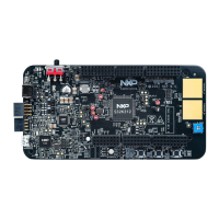
S32K312EVB-Q172 | S32K312EVBQ172ND - Hardware User Manual
S32K312EVB-Q172
S32K312EVBQ172ND
HWUM
All Information provided in this document is subject to legal disclaimers
© NXP B.V. 2020. All rights reserved
LPUART9_RX is routed to LIN Phy0
LPUART9_TX is routed to LIN Phy0
LPUART5_RX is routed to LIN Phy1
LPUART5_TX is routed to LIN Phy1
ADCPOT0 [R293] is routed to PTA11 - ADC1_S10
6 S32K312EVB-Q172 - Startup
Follow these steps to connect and power on the board
1. Carefully unpack the S32K312EVB-Q172 and observe ESD preventive measures while handling the K3 development board.
2. Connect necessary cables between host PC and EVB board prior to applying power to the EVB.
3. The power-ON sequence for the EVB must be as follows:
 Loading...


