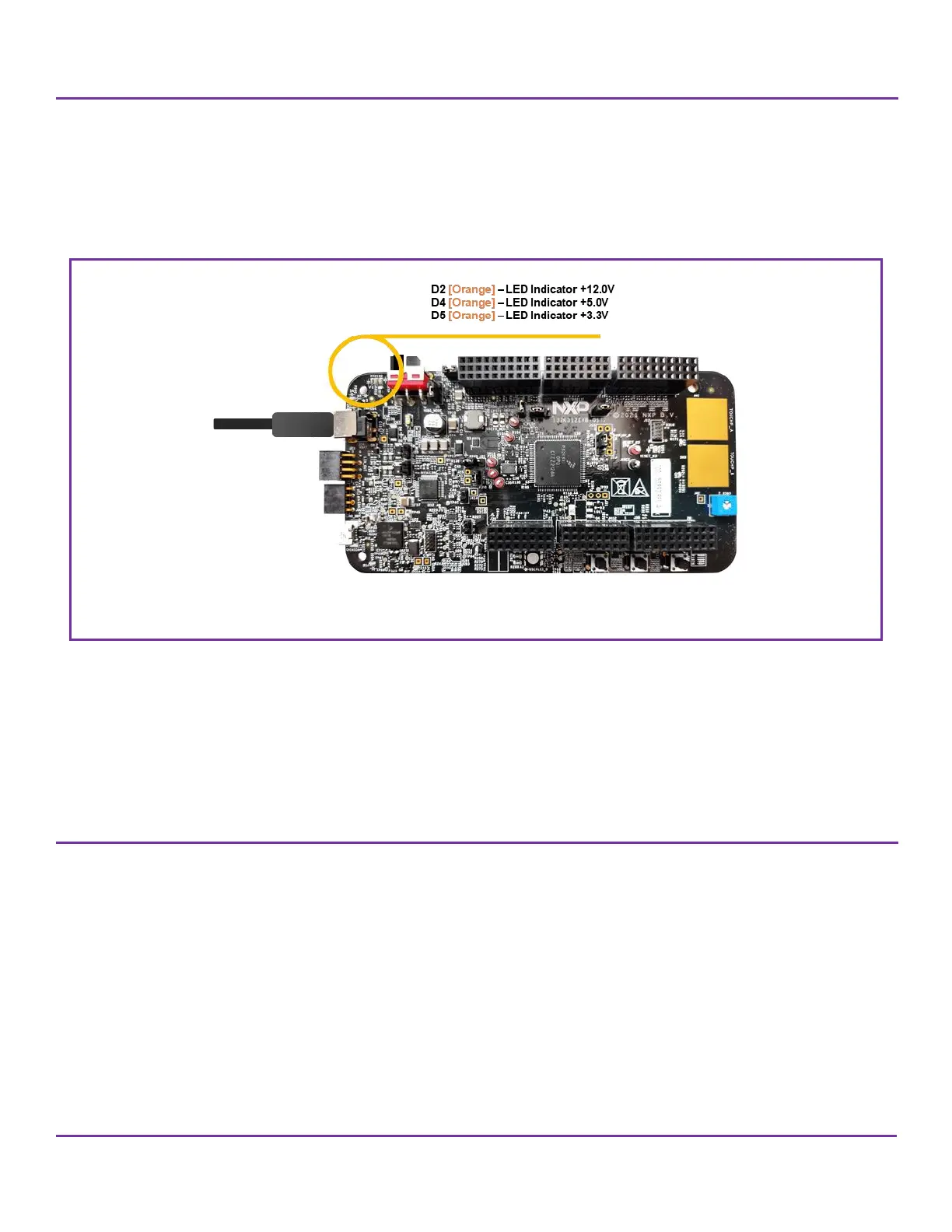
4. When power is applied to the EVB, three orange LED’s adjacent to the voltage regulators show the presence of the supply
voltages as follows:
• LED D2 Indicates that the 12.0V is connected to the EVB correctly.
• LED D4 Indicates that the 5.0V linear regulator is enabled and working correctly.
• LED D5 Indicates that the +3.3Vlinear regulator is enabled and working correctly.
If no LED’s are illuminated when power is applied to the EVB and the regulators are correctly enabled using the appropriate
jumpers, it is possible that either power supply is not connected properly, or the voltage level is lower that the specified [+12.0V
to ≥2Amps].
Note that the fuse will not protect against one of the EVB regulators being shorted. If this happens, damage is likely to occur to
the EVB and / or components.
5. The board is ready to use now.
7 S32K312EVB-Q172 - Power supply
The EVB requires an external power supply voltage of between to +12V/≥2A. This allows the EVB to be easily used in a
vehicle if required. The 12v input is on the EVB is used to supply a FS26/SBC – U1, the power management IC controller
provides +5.0V, +3.3V and +1.5V, for the different power configurations of VDD_HV_A, VDD_HV_B, V15 and other
interfaces
 Loading...


