Operating & Maintaining the Connex500/350 3-D Printer
7–32
DOC-13000 Rev. E
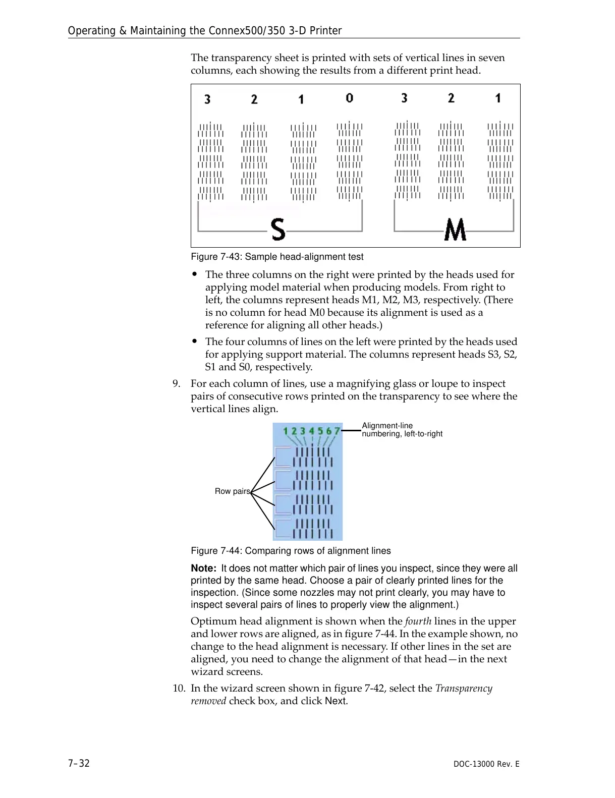
Thetransparencysheetisprintedwithsetsofverticallinesinseven
columns,eachshowingtheresultsfromadifferentprinthead.
Figure 7-43: Sample head-alignment test
• Thethreecolumnsontherightwereprintedbytheheadsusedfor
applyingmodelmaterialwhenproducingmodels.Fromrightto
left,thecolumnsrepresentheadsM1,M2,M3,respectively.(There
isnocolumnforheadM0becauseitsalignmentisusedasa
referenceforaligningallotherheads.)
• Thefourcolumnsoflinesontheleftwereprintedbytheheadsused
forapplyingsupportmaterial.ThecolumnsrepresentheadsS3,S2,
S1andS0,respectively.
9. Foreachcolumnoflines,useamagnifyingglassorloupetoinspect
pairsofconsecutiverowsprintedonthetransparencytoseewherethe
ve
rticallinesalign.
Figure 7-44: Comparing rows of alignment lines
Note: It does not matter which pair of lines you inspect, since they were all
printed by the same head. Choose a pair of clearly printed lines for the
inspection. (Since some nozzles may not print clearly, you may have to
inspect several pairs of lines to properly view the alignment.)
Optimumheadalignmentisshownwhenthefourthlinesintheupper
andlowerrowsarealigned,asinfigure 7‐44.Intheexampleshown,no
changetotheheadalignmentisnecessary.Ifotherlinesinthesetare
aligned,youneedtochangethealignmentofthathead—inthenext
wizardscreens.
10
. Inthewizardscreenshowninfigure 7‐42,selecttheTransparency
removedcheckbox,andclick
Next.