Do you have a question about the OEG KSW-E and is the answer not in the manual?
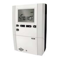
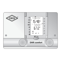
Details the physical design and components of the KSW-E, KSW, and KS2W controllers.
Explains the various symbols used on the controller's graphic LCD display for operation and status.
Lists and describes symbols related to the controller's operational modes, such as automatic and manual.
Details symbols representing temperature readings and other data displayed on the controller.
Explains symbols indicating errors, warnings, and critical conditions detected by the controller.
Provides a detailed explanation and breakdown of the controller's main display interface and its elements.
Guide on how to select the desired language for the controller interface.
Instructions on selecting the appropriate hydraulic scheme for the controller's configuration.
Explains how to access and navigate the user settings menu using the controller's buttons.
Describes the main sections of the user settings menu, including temperature, operation, and time programs.
Details user functions like hot water warming and basic settings such as language and time.
Overview of advanced controller parameters and auxiliary tools, grouped into Basic, Service, and Function parameters.
Tools for resetting parameters, time programs, and managing user settings.
How to set desired temperatures for sensors using the controller interface.
Details the different operating modes like automatic, manual, and switch-off.
Step-by-step guide to edit or copy time programs for different days.
Interface and process for editing and copying daily time programs.
Displays default switch-on intervals for time programs 1, 2, 3, and legionella protection.
Details user functions for immediate hot water warming and holiday mode operation.
Procedures for selecting language and setting the controller's time and date.
Settings for screen illumination duration, intensity, and display contrast.
Access to data on acquired energy, temperature diagrams, and output operation times.
Details parameters for differences, hysteresis, and temperature limits for sensors.
Details service parameters for hydraulic schemes, pump operation, and system configurations.
Covers parameters for heat metering, medium selection, sensor configuration, and relay output programming.
Options to reset parameters for selected schemes or all controller settings.
Functions to save or load user-defined settings.
Procedure for physically mounting the controller on a wall.
Important safety warnings and diagrams for electrical connections.
Details on sensor types, wire cross-sections, and cable lengths.
Statements regarding compliance with EU directives and product warranty terms.
Sections for recording controller type, initial setup, and changes to factory settings.
| Brand | OEG |
|---|---|
| Model | KSW-E |
| Category | Controller |
| Language | English |