44952001TH Rev.2
4-34
Oki Data CONFIDENTIAL
4.REPLACEMENT OF PARTS
Air
Air
10
18
12
9
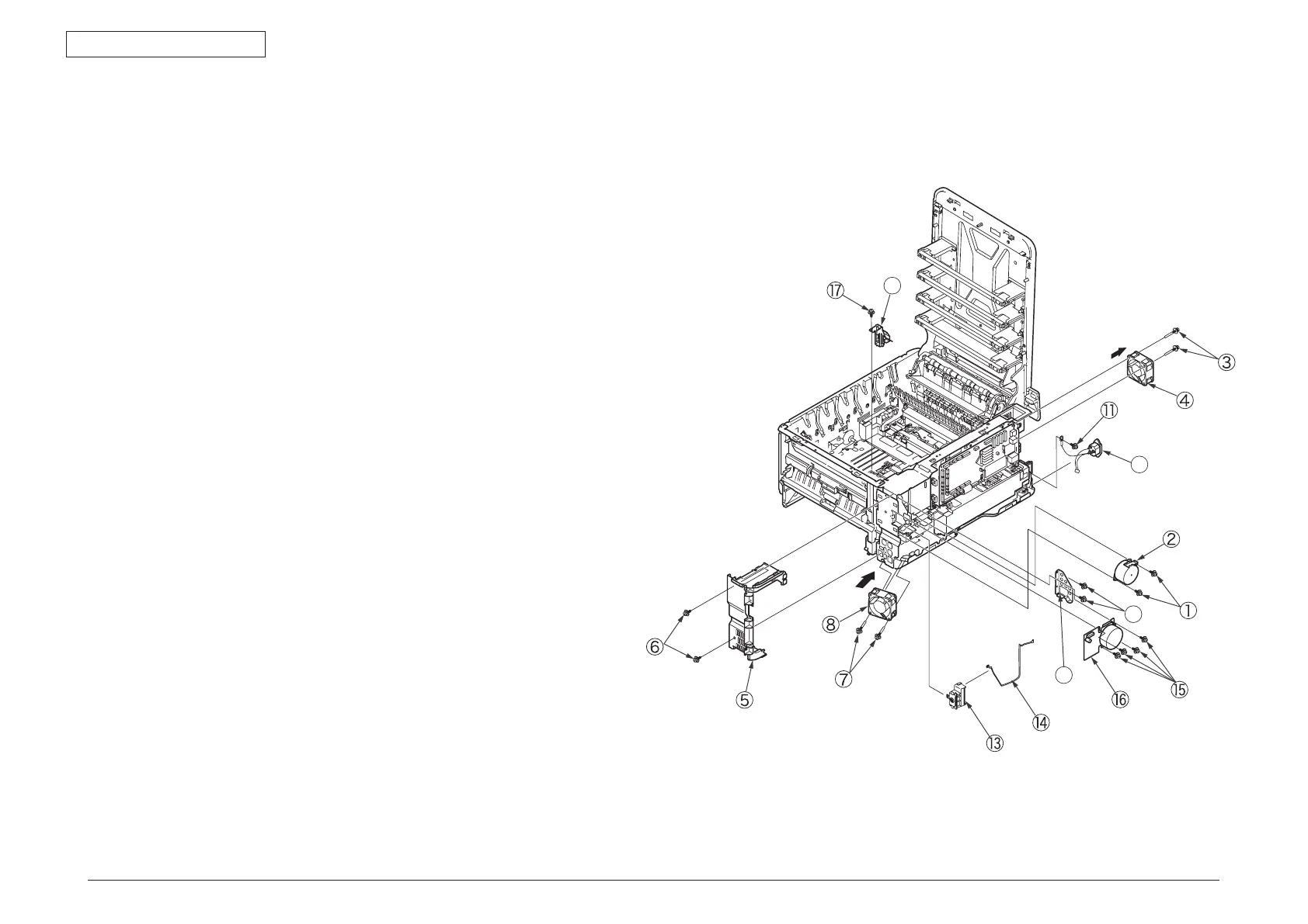
4.2.15 Front fan, hopping motor, rear fan, image drum
motor and cover-open switch
(1) Remove the left side cover, the right side cover, the rear cover, the MPT assembly,
the plate-rear, the plate shield assembly, low voltage power supply and the cover
front assembly.
(2) Remove the two (silver-colored) screws
①
to detach the hopping motor
②
.
(3) Remove the two (silver-colored) screws
③
to detach the rear fan
④
.
(4) Remove the two (silver-colored) screws
⑤
and unlatch the frame-MPT-side
⑥
to
remove it.
(5) Remove the two (silver-colored) screws
⑦
to detach the front fan
⑧
.
(6) Remove the two (silver-colored) screws
⑨
to detach the plate support
⑩
.
(7) Disconnect the CONN Cord
⑬
from the CU/PU PCB.
(8) Remove the (FG) screw
⑪
.
(9) Remove the AC inlet
⑫
and the Holder Assy.-Switch
⑬
with the CONN Cord
⑭
from the side R of the mainbody.
(10) Disconnect the CONN Cord
⑭
from the Holder Assy.-Switch
⑬
.
(11) Remove the four (silver-colored) screws
⑮
to detach the image drum motor
⑯
.
(12) Remove the screw
⑰
to detach the cover-open switch
⑱
.
Note!
•NotetheairowdirectionoftheseFANstoassemble.
•WhileremovingorinstallingFAN
④
,
⑧
do not press impeller of the FAN.
In case of the impeller unfastened by mistake, do not reuse it and install a new FAN.