1
-5-23
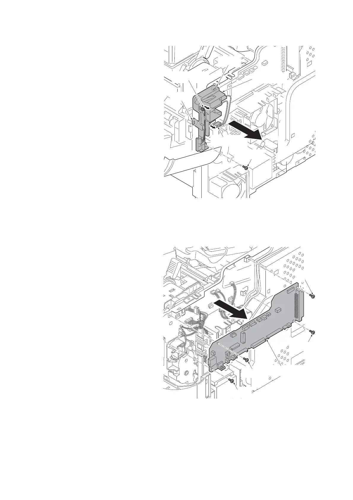
8. Pull two connectors out.
9. Remove the screw and two hooks a
nd
then remove the wire guide.
Figure 1-5-35
10. Pull all connectors out from main PWB.
11. Remove four screws and then remo
ve
the
engine PWB.
12. Check or replace the engine PWB and
refit all the
removed parts.
NOTE: When replacing the PWB, remove the
EEPROM from the PWB and then reattach it to
the new PWB.
Figure 1-5-36
Hook
Connector
Connector
Wire guide
Hook
Screw
Engine PWB
Screw
Screw
Screw
Screw