1
-2-12
1-2-3 Installing the optional equipment
(1) Expansion memory
Procedure
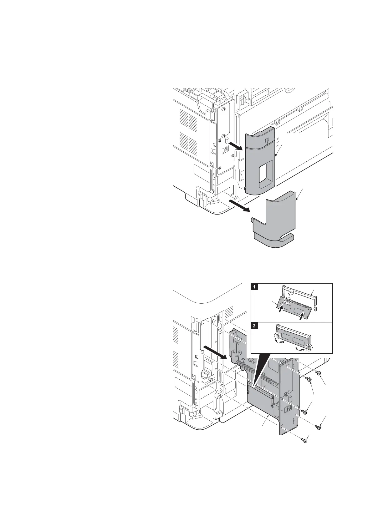
1. Remove the inlet cover.
2. Remove the slot cover.
3. Unplug the power cable.
Caution: Do not insert or remove ma
in
PWB assembly w
hile machine powe
r is
on
.
Doing so may cause damage to th
e
ma
chine and the main PWB.
Figure 1-2-21
4. Remove five screws and then remove
the main PWB assembly.
5. Aligning the cutouts of the memo
ry
mo
dule with the matching keys of th
e
socket, carefully
plug the memory mod-
ule into the memory socket until it clicks
in place.
6. Then, push down the memory modu
le
to secure.
7.
Refit the main PWB assembly and th
e
screw
s.
8. Refit the covers.
9. Plug the printer into a power outlet.
10. Print a status page to check the mem-
ory expansion. (See page 1-3-2)
If memory expansion has been proper
ly
p
erformed, information on the insta
lled
memory is printed with
the total memo
ry
cap
acity has been increased.
Standard memory capacity 256 MB
.
Figur
e 1-2-22
Slot cover
Inlet cover
Expansion
memory
Memory socket
Screw
Screw
Screw
Screw
Main PWB
Assembly