1
-5-27
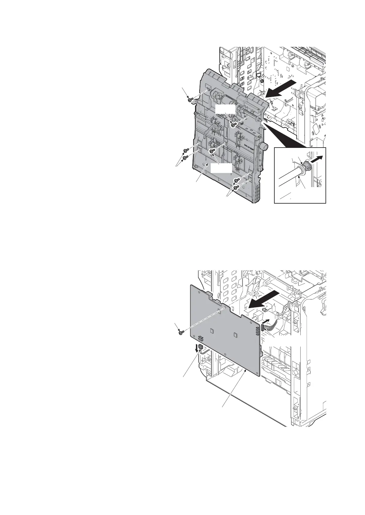
9. Remove seven screws.
10. Extract the feed roller axis by pushin
g
the joint p
art.
11. Remove the DU assy to the front.
Figure 1-5-43
12. Remove the screw.
13. Pull two connectors out and then
remove the high voltage PWB.
14. Check or replace the high voltag
e PWB
an
d refit all the removed parts.
Figure 1-5-44
Screws
Screw
DU assy
Screw
Screw
Screws
Paper feed
roller axis
Joint part
High voltage PWB
Connector
Connector
Screw