1.
Turn on the control box.
2.
Control each unit using RS-232C communication commands from a PC.
For details on RS-232C communication commands, refer to the command reference manual.
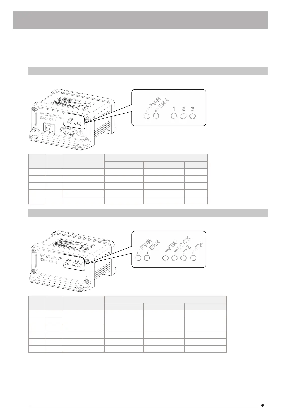
4.1 Status display of the indicators on BXC-CBB
The following table shows the status display of each indicator.
Symbol Color Displays the status of
Status
●Off ○On ◎ Flashing
PWR Green Power supply Power off Power on —
ERR Red Fatal error No error Fatal error occurred —
1 Green Back connector 1 No unit connected Unit connected —
2 Green Back connector 2 No unit connected Unit connected —
3 Green Back connector 3 No unit connected Unit connected —
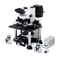
4.2 Status display of the indicators on BXC-CBE1
The following table shows the status display of each indicator.
Symbol Color Displays the status of
Status
●Off ○On ◎ Flashing
PWR Green Power supply Power off Power on —
ERR Red Fatal error No error Fatal error occurred —
FSU Green Sensing unit for AF No unit connected Unit connected Control malfunction
LOCK Green Safety lock Open state Short-circuit state Control malfunction
Z Green Reserved by maker — — —
FW Green Filter wheel No unit connected Unit connected Control malfunction
4. Operation procedures
27
4. Operation procedures 4.1 Status display of the indicators on BXC-CBB