28
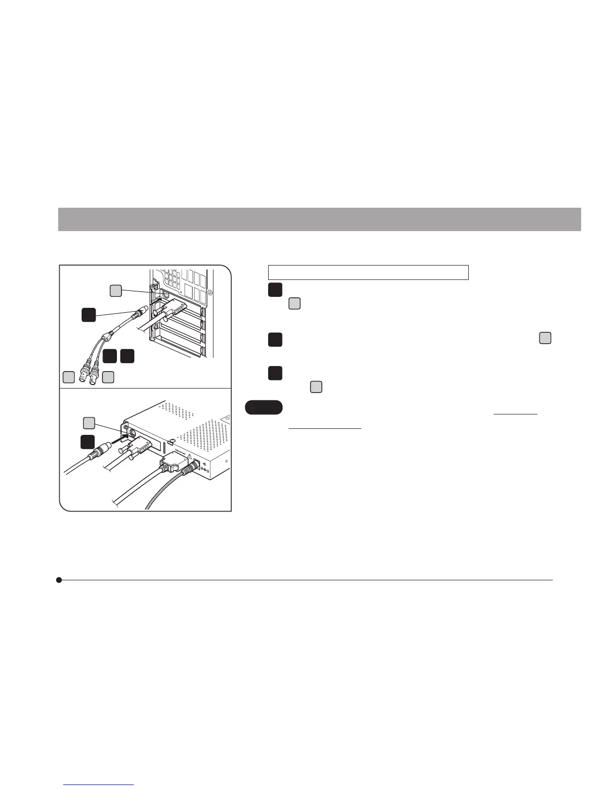
Fig. 13
DP73
Connecting the External Trigger Cable (Fig. 13)
Insert the connector of the external trigger cable to the connector
a
on the PCIe interface board in the computer or the PCIe
extension box.
When using the trigger input, connect the red cable (marked “I” )
b
to the BNC connector.
When using the trigger output, connect the white cable (marked
“O” )
c
to the BNC connector.
The external triggering is available only when the cellSens /
OLYMPUS Stream software is run.
1
2
3
CAUTION
1
1
2 3
Computer
PCIe Extension Box
a
a
b c