36
ASSEMBLY
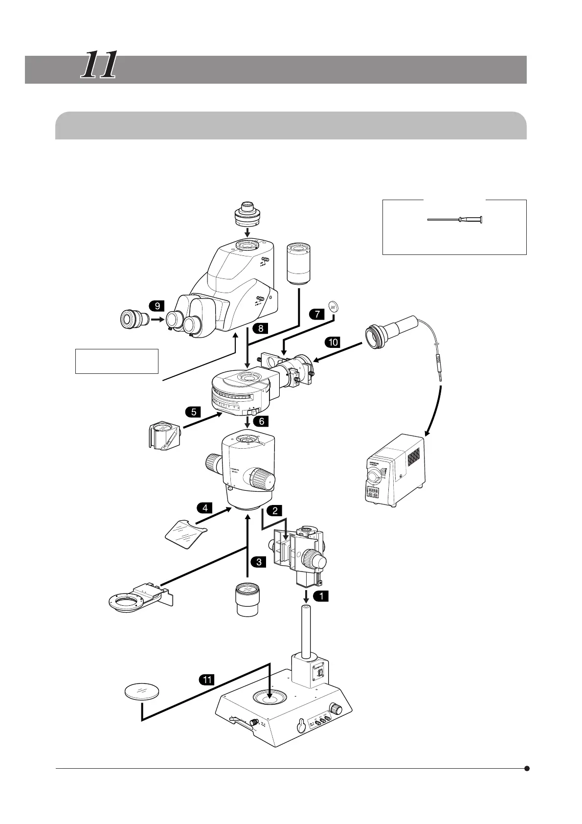
11-1 Assembly Diagram
The diagram below shows how to assemble the various modules. The numbers indicate the order of assembly.
# When assembling the microscope, make sure that all parts are free of dust and dirt, and avoid scratching any
parts or touching glass surfaces.
Eyepieces
WHN10X-H
Tilting Trinocular Head
MVX-TTRS
To be assembled by
the dealer
Magnification Changer*
MVX-CA2X
Fluorescence mirror units
U-MCFPHQ/XL
U-MGFPHQ/XL
U-MYFPHQ/XL
U-MRFPHQ/XL
U-MGFP/XL
U-MGFPA/XL
UV shield plate
Revolving Nosepiece*
MVX-2RE
Objective Lens
MVPLAPO 0.63X
MVPLAPO 1X
MVPLAPO 2XC
Stage Glass & base
accessories*
Camera Adapter
MVX-TV1XC
MVX-TV0.63XC
MVX-TV1XB
Tube Lens Unit
MVX-TLU
ND Filter
32ND6
32ND12
32ND25
32ND50
Liquid light guide adapter
U-LLGAD
High-Intensity Lamp Housing
U-LH100HG
U-LH100HGAPO
U-LH75XEAPO
Coaxial Fluorescence
Illuminator
MVX-RFA
Zoom Microscope
Body
MVX-ZB10
Focusing Assembly
MVX-FOF
Light Source
SZX illumination base
SZX-ILLK/ILLB2/ILLD2
Large Base
SZX-STL
The assembly methods of the modules marked * are described in Chapter 10, “OPERATION OF OTHER MODULES”.
Required tools
Allen screwdriver
(provided with the zoom microscope body)