6
The controller functions are user selectable. It is therefore the
user's responsibility to ensure that the controller configuration
corresponds to the factory's requirements and is safe. Remove the
parameter lock jumper to restrict tampering after configuration.
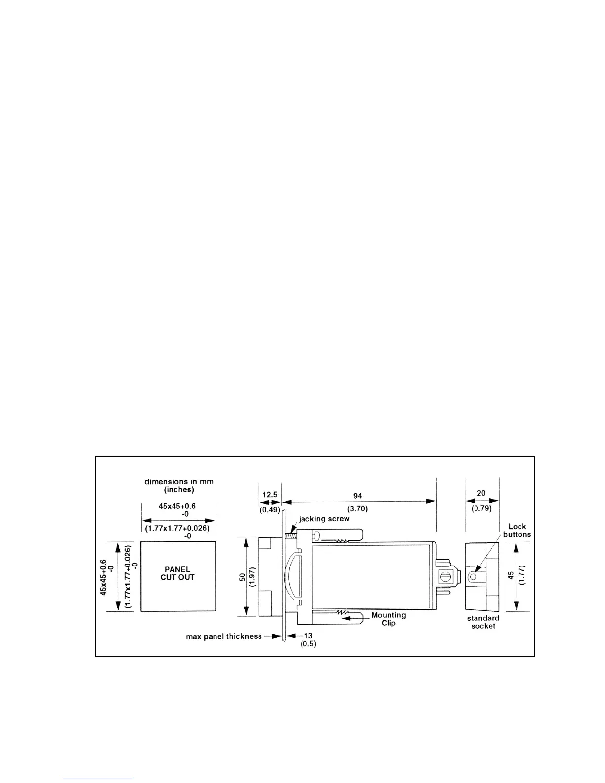
The CN9000A is mounted in a panel through a 1.772" (45 mm)
square
1
/
16
DIN 43700 cutout using the speciai mounting clip
provided (refer to Figure 2-1).
To install the CN9000A, remove the rear socket by pressing the
lock buttons. Slide the controller into the panel cutout from the
front. Slide the mounting clip back onto the controller from the rear.
Press to home position until the clip holds the unit firmly in place. If
necessary, the mounting can be further tightened using the jacking
screws. Plug the rear socket back into place on the controller.
To remove the controller from the panel, pull the legs of the
mounting clips away from the controller case to release the
ratchet.
The minimum spacing for mounting several controllers is shown in
Figure 2-2.
CONFIGURATION CAUTION
MOUNTING INSTRUCTIONS
*To unplug socket, press in lock buttons and pull apart
Figure 2-1. Controller Mounting and Panel
Cutout Dimensions
 Loading...