EasyManuals Logo

Omega C9000A SERIES User Manual

Omega C9000A SERIES
92 pages
To Next Page IconTo Next Page
To Previous Page IconTo Previous Page
Page #15 background imageLoading...
Page #15 background image
9
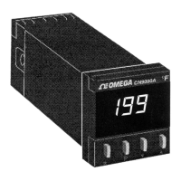
Figure 2-4. Thermocouple and RTD Input Wiring
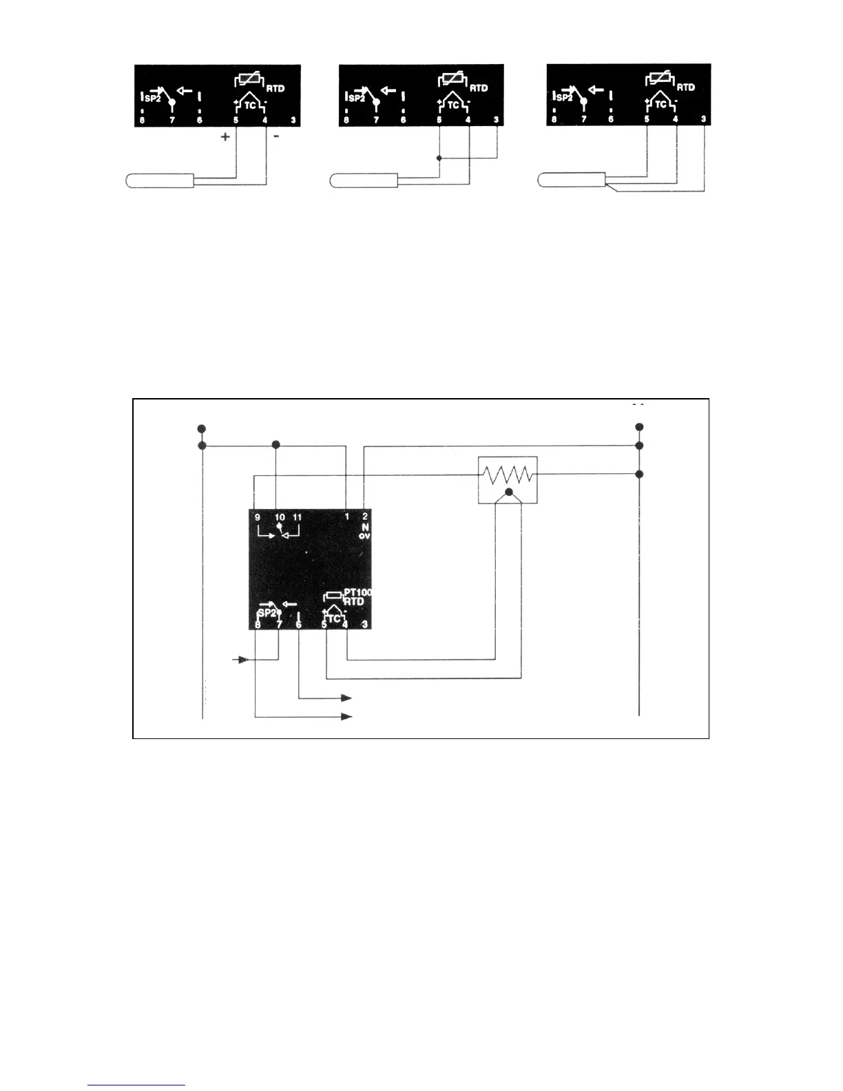
Figures 2-5 and 2-6 illustrate typical wiring of the CN9000A
Controllers. (Standard controllers operate on 115VAC 50/60Hz.
230VAC operation is optional.)
Connections for
Thermocouple
Connections for
2-wire Pt 100/RTD
Connections for
3-wire Pt 100/RTD
2.4 TYPICAL WIRING DIAGRAMS
Figure 2-5. Wiring Heater with Alarms
(Two Mechanical Relays-Model CN9111A)
LOW ALARM OR WITHIN LIMITS SIGNAL
HIGH ALARM OR OUT OF LIMITS SIGNAL
ALARM
SIGNAL
SUPPLY
LOAD
5A (max
115V±15% 50-60 Hz
N
L

Table of Contents

Questions and Answers:

Question and Answer IconNeed help?

Do you have a question about the Omega C9000A SERIES and is the answer not in the manual?

Omega C9000A SERIES Specifications

General IconGeneral
BrandOmega
ModelC9000A SERIES
CategoryTemperature Controller
LanguageEnglish

Related product manuals