13
TABLE 3-1 (Cont'd)
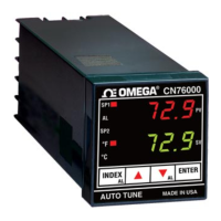
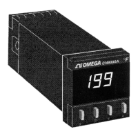
All three Error Indicator LEDs are
on when unit is in Manual or Park
Mode.
This LED is illuminated (green)
when the SP1 output is ON.
This LED is illuminated (red) when
the SP2 output is ON or OFF,
depending on mode of operation.
Refer to Function .31 in Table 3-6
for more details.
NOTE: The Parameter lock jumper is located under the lower front
bezel (discussed in Section 3.13).
ITEM CONTROL/INDICATOR FUNCTION
3 SP1 Output Indicator
4 SP2 Output Indicator
5 Control Keys
When pressed, displays the
SP1 temperature.
Pressed simultaneously
increases the SP1
temperature value.
Pressed simultaneously
decreases the SP1
temperature value.
Selects Set-Up Mode (entry
into the Function and
Option commands -refer to
Table 3-4). Display flashes,
normal temperature control
is maintained.
When in the Set-Up Mode,
increments the Function
and Option numbers up or
down.
When in Set-Up Mode,
changes the sub mode from
Functions to Options and
vice-versa.
★
★
★
P
or
★
 Loading...