2.4.4 Frame types
Protocol frames have a structure made of ‘Header’, ‘Data’ and ‘Trail’.
Secon ‘Header’
Contains the start byte (‘STX’), the frame idener (‘ID’), the origin
address (‘FROM’) and the desnaon address (‘TO’), the register id
(‘REG’) and the length (‘LONG’) of the ‘Data’ secon.
Secon ‘Data’
Contains data for the requested register (‘REG’).
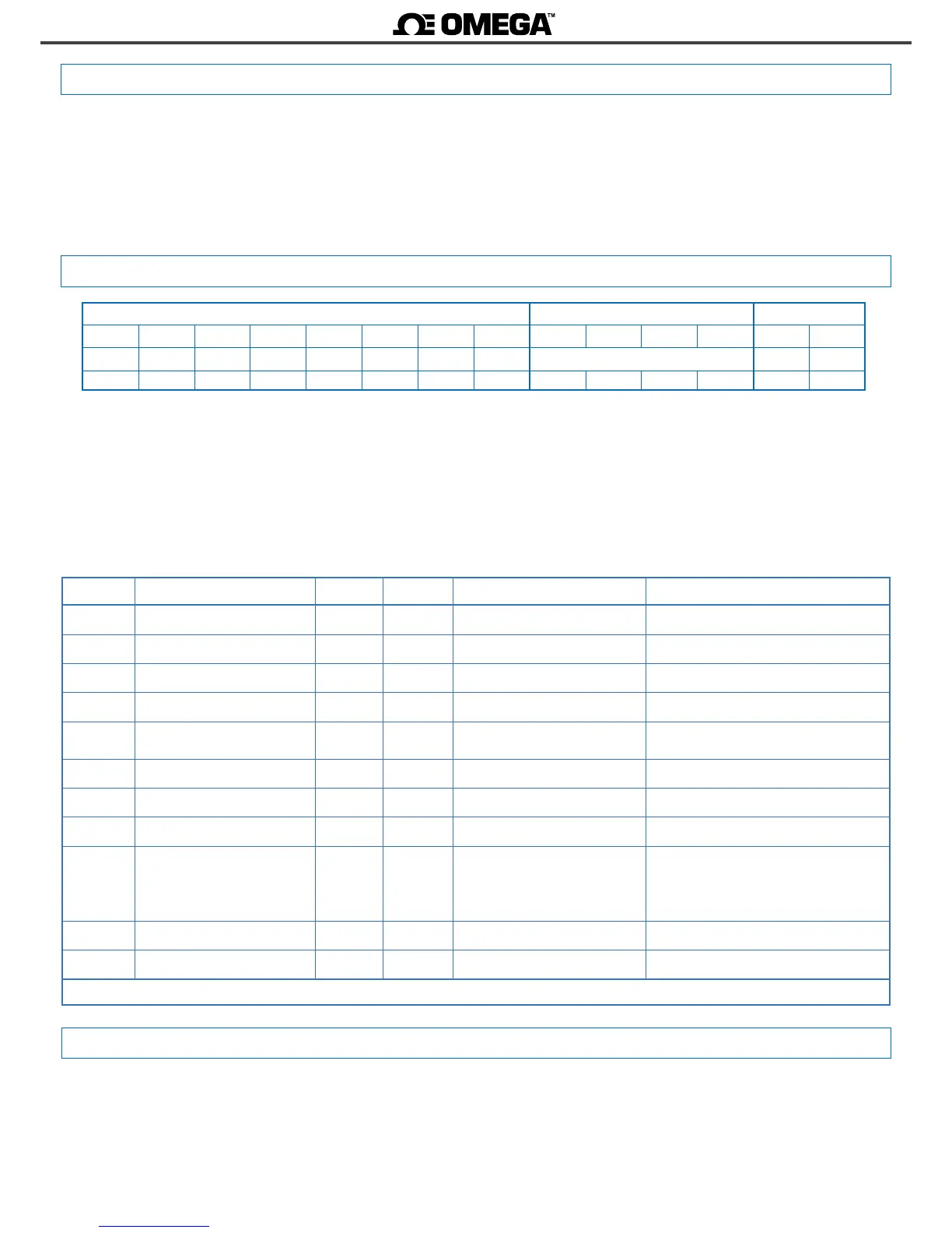
Header Data Trail
STX ID RSV FROM TO REG RSV LONG D0 D1 ... Dn CRC ETX
2 x 32 x x x 32
n+1 [data] x 3
0 1 2 3 4 5 6 7 8 9 ... n+7 n+8 n+9
Field Descripon Size Posion Real value Frame value
STX Start of frame 1 byte 0 does not apply 2
ID Frame type 1 byte 1 (see secon 2.4.4) real_value
RSV Reserved 1 byte 2 0 32
FROM Origin address 1 byte 3 0 (‘Master’) / 1 to 31 (‘Slave’) 32 + real_value
TO Desnaon address 1 byte 4 0 (‘Master’) / 1 to 31 (‘Slave’)
128 (‘broadcast’)
32 + real_value
REG Register idencaon 1 byte 5 (see secon 2.4.1) 32 + real_value
RSV Reserved 1 byte 6 0 32
LONG Length of ‘Data’ secon 1 byte 7 n (between 0 and 32) 32 + real_value
D0 … Dn Data n bytes 8 to n+7 number 0 to 9
decimal point
polarity (+/-)
ASCII code of the number (48 to 57)
ASCII code of decimal point (46)
ASCII code of ‘+’ (43)
ASCII code of ‘-’ (45)
CRC CRC calculaon 1 byte n+8 does not apply (see secon 2.4.8)
ETX End of frame 1 byte n+9 does not apply 3
Table 15 - Descripon of the bytes for the ASCII frame
Secon ‘Trail’
Contains the ‘CRC’ code and the end of frame byte (‘ETX’).
‘Real value’ and ‘Frame value’
To use representable ASCII values, the real values are codied before
being sent into the frame. The following denions apply :
• ‘real value’ is the value of the eld without codicaon
• ‘frame value’ is the value of the eld, codied
2.4.5 Frame structure
The ASCII protocol denes the following frames:
• Frame ‘read’ (‘RD’). Id code 36. Request data frame. The requested
register is indicated into the ‘REG’ byte (‘Header’ secon).
• Frame ‘answer’ (‘ANS’). Id code 37. Response frame to a request
data frame. The requested register is indicated into the ‘REG’ byte’
(‘Header’ secon). Data of the requested register is indicated into
data bytes ‘D0’ to ‘Dn’ (‘Data’ secon).
• Frame ‘error’ (‘ERR’). Id code 38. Response frame to a request data
frame. Indicates that an error has occurred. Error code is codied
into the ‘REG’ byte (‘Header’ secon).
• Frame ‘ping’ (‘PING’). Id code 32. Used to conrm the existence of
the remote instrument.
• Frame ‘pong’ (‘PONG’). Id code 33. Response to a ‘ping’ frame. It
conrms the existence of the remote instrument.
2.4.6 Error codes
Frames ‘ERR’ contain within the ‘REG’ eld, the error code. Available
error codes are :
error 1 unknown register
error 2 display overrange
error 3 display underrange
error 4 CRC error
error 5 internal error

 Loading...


