The R1, T1 and SSR modules provides 1 relay output, 1 transistor out-
put or 1 SSR drive output, to install in DPF20 digital panel meters, up
to a maximum of 3 modules in a single meter.
Note : for more than three relays per instrument or larger relay den-
sity per module, see special modules R2, R4 and R6.
Conguraon is performed from the frontal keypad of the meter,
by seng the parameters at the alarms conguraon menu (‘ALr.1’,
‘ALr.2’ or ‘ALr.3’ depending on the posion the module is installed).
2. Output and control modules
Opon T1
Output type transistor
Maximum voltage 35 Vdc
Maximum current 50 mA
Isolaon 3500 Ve
Type of terminal plug-in screw terminal
pitch 5.08 mm
Installaon allowed at ‘Opt.1’, ‘Opt.2’, ‘ Opt.3’
Opon SSR
Output type to control a SSR relay
Output voltage +15 Vdc
Maximum current 45 mA
Isolaon 1000 Vdc
Type of terminal plug-in screw terminal
pitch 5.08 mm
Installaon allowed at ‘Opt.1’, ‘Opt.2’, ‘ Opt.3’
Opon R1
Output type relay
Relay type
3 contact relay (NC, NO, common)
Maximum current 8 A (resisve load)
Maximum voltage 250 Vac connuous
Isolaon 3500 Ve
Type of terminal plug-in screw terminal
pitch 5.08 mm
Installaon allowed at ‘Opt.1’, ‘Opt.2’, ‘ Opt.3’
Power
Opt.2
Opt.1
Opt.3
A B C
A B C
Signal
A B C
Rear view DPF20
The menu allows to congure the setpoint, hysteresis, independent
acvaon and deacvaon delays, and a second setpoint to create
alarm windows.
Modules R1, T1 and SSR are isolated against all other instrument cir-
cuits, and isolated between them.
Modules R1, T1 and SSR can be ordered pre-installed into a DPF20
digital panel meter, or standalone for delayed installaon, as they do
not require soldering or special conguraon.
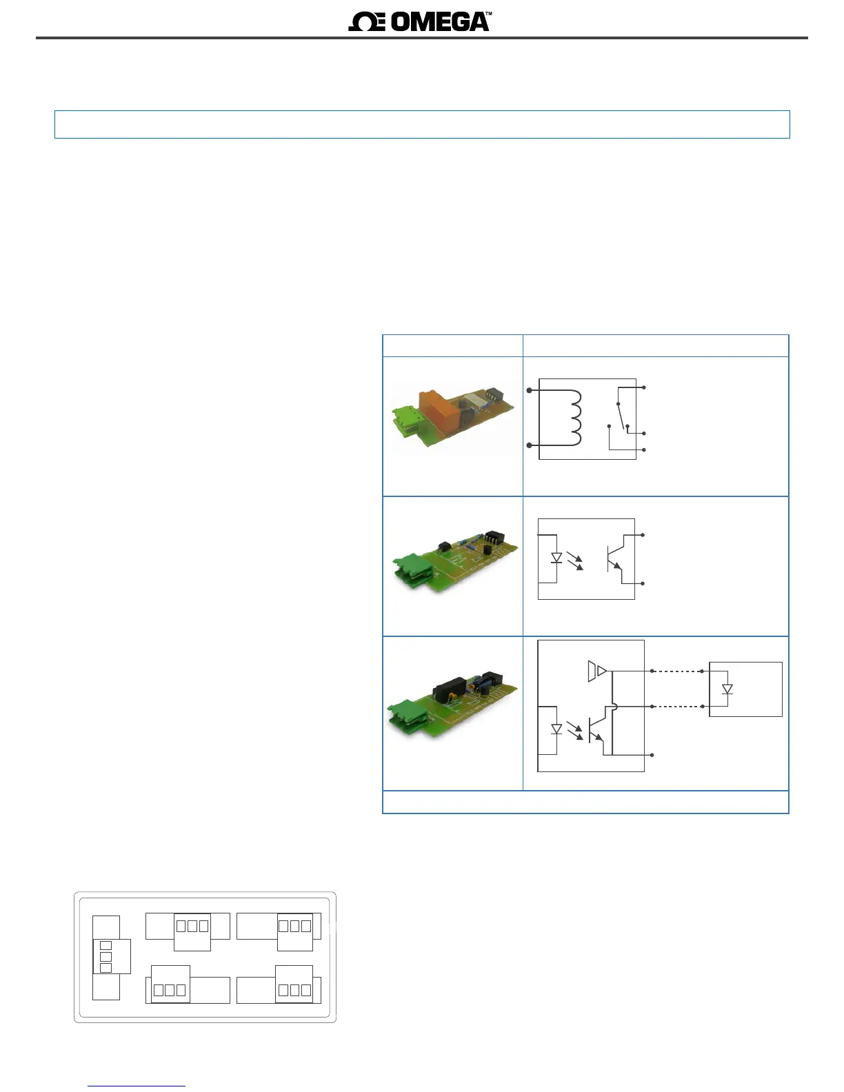
Module Output schemacs and connecons
Module R1 - Relay output
‘com’ (‘A’)
‘NC’ (‘C’)
Schemac for R1 output
‘NO’ (‘B’)
Module T1 - Transistor output
‘B’
‘A’
Schemac for T1 output
Module SSR - SSR drive out
put
Schemac for SSR drive output
‘B’
‘A’
SSR relay
+15 Vdc ‘C’
Table 7 - Connecons
2.1 Módules R1, T1 and SSR

 Loading...


