Special working mode for applicaons with low frequency signals.
Applies to ratemeter (‘rt.6’), ratemeter quadrature (‘rtq.7’) and peri-
odmeter (‘Prd.8’). The ‘SLOW’ mode allows to measure slow fre-
quencies down to 1 mHz (0,001 Hz) and is funconal up to 200 Hz.
The ‘SLOW’ mode provides the fastest response me possible for a
given applicaon, calculang the frequency and the period based on
the me between consecuve impulses.
The ‘SLOW’ mode needs to dene the parameter ‘maximum waing
me’ to a value between 1 and 1000 seconds. If this me expires
without a single impulse being received, the reading jumps to ‘0’
(both for ratemeter and periodmeter modes). The ‘GATE’ parameter
is not used if ‘SLOW’ mode is acve.
In ‘ratemeter quadrature’ (‘rtq.7’) mode, the acvaon of the
‘SLOW’ mode calculates the frequency based on the me between
consecuve impulses received on channel A, and calculates the
sense of turn (clockwise or counter-clockwise) by comparing each
impulse with the state of channel B. The ‘edge’ parameter is xed to
a ‘1--1’. Typical applicaon for quadrature frequency measure with
two inducve sensors at low frequency.
1.13 Funcon ‘Trigger Sense’
Special working mode for counter applicaons with high frequency
signals, up to 250 KHz. Applies only to the counter mode (‘cn.1’).
The acvaon of the ‘FAST’ mode congures the signal detecon by
rising edge. The rst edge detected, either rising or falling edge, aer
the instrument restart (power-up, or conguraon change) is used
for internal inializaon and will not be counted as impulse.
1.14 Funcon ‘cycle counter’ 1.15 ‘SLOW’ mode
The trigger level is automacally congured when selecng a sensor
from the ‘Sensor / Conguraon’ (‘SnSr’ / ‘Auto’) menu list. The trig-
ger level can be also manually modied from the ‘SnSr’ / ‘TrIG’ menu
entry. The selected value applies to channels ‘A’ and ‘B’ (the reset has
a xed trigger level at 2.5 Vdc).
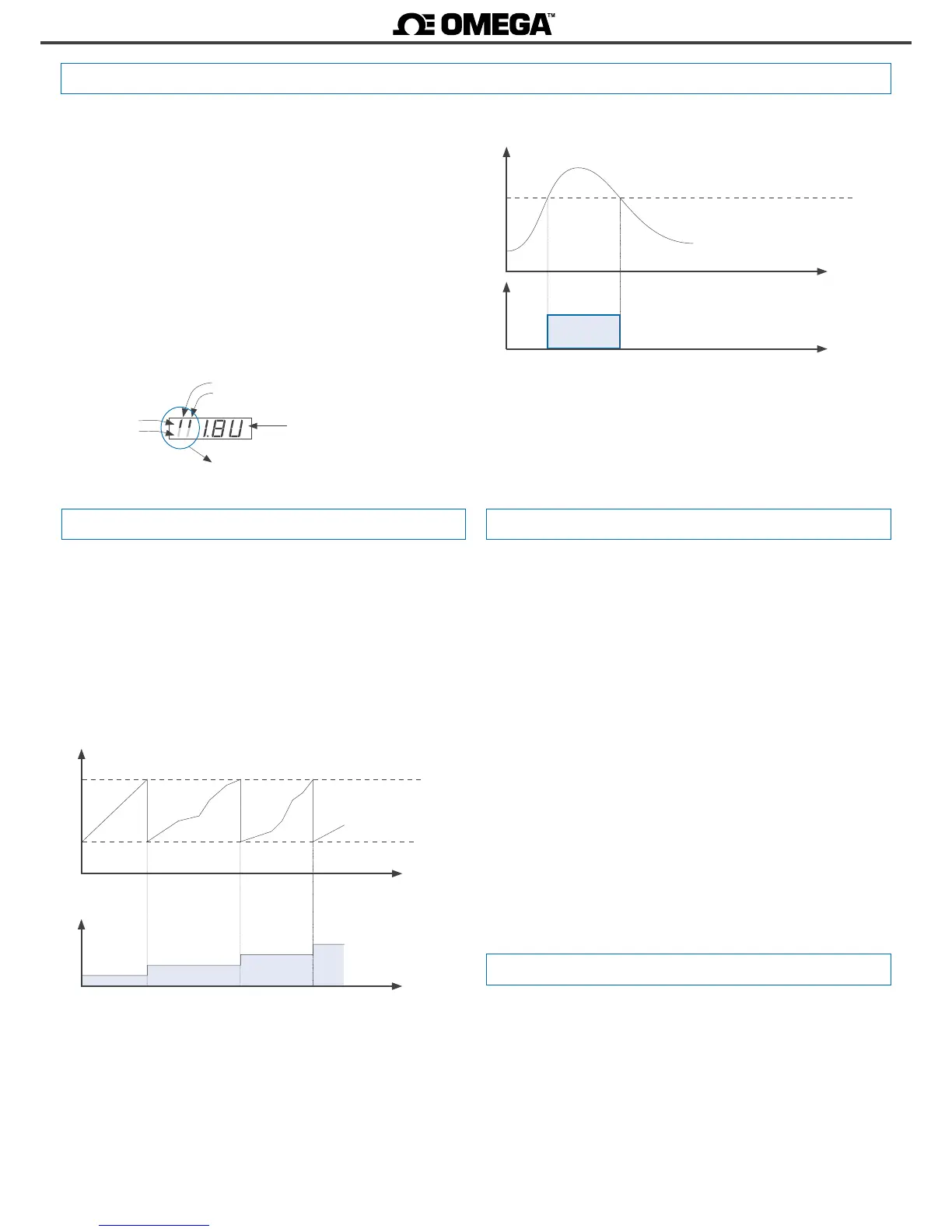
At the ‘SnSr’ / ‘TrIG’ menu, the instrument shows the trigger level
and two vercal leds to the le. These leds inform in real me about
the status (‘0’ or ‘1’) of the input channels ‘A’ and ‘B’. When the led
switches between up and down posion, it indicates that impulses
are being detected at the input. If the instrument does not detect
impulses, the led posions remain xed.
Increase the trigger level pressing key ‘UP’ (5) and decrease press-
ing key ‘LE’ (3).
Vdc
Time
Trigger level
‘1’
‘0’
Signal detected
channel ‘A’
Status ‘1’
Trigger level
Status ‘0’
Leds of the ‘Trigger
Sense’ funcon
channel ‘B’
1.16 ‘FAST’ mode
Reading
Time
Setpoint 1
Impulse counter, with ‘reset to preset’
when setpoint 1 is reached
Preset
Time
Cycle counter
0
1
2
3
The counter modes allow to acvate a reset funcon (to ‘0’ or to
‘preset’ value) when an alarm setpoint is reached. With this congu-
raon, the instrument counts in cycles, counng from the instrument
preset value up to the alarm setpoint. Each cycle is counted and ac-
cumulated into an internal memory, accessible through the ‘fast ac-
cess’ menu (key UP (5) (see secon 1.19.12)).
To reset the memory of cycles, visualize the value at the ‘uP’ menu,
then press the (5) key and the ‘rSt’ message appears. Press (<) to
reset.

 Loading...


