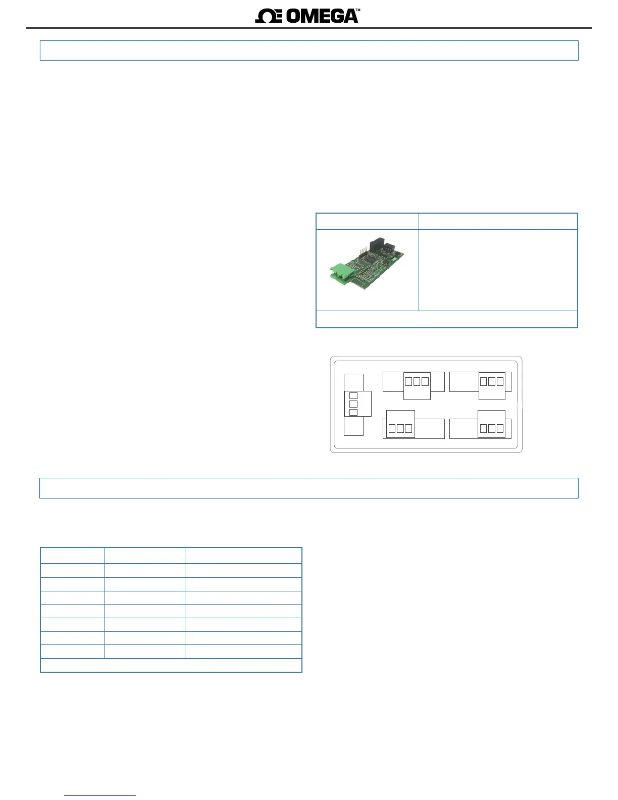
2.4 Module S4
Opon S4
Output type RS-485 ASCII communicaon port
Bus RS-485
Speed 57.6 Kbps to 600 bps
Data format 8n1 (standard), 8o1, 8n2, 8e1
Protocol ASCII
Architecture ‘master - slave’
Addresses 01 to 31
‘Broadcast’ address 128
Registers see secon 2.4.1
Isolaon 1000 Vdc
Conguraon 3 buon front keypad
Temperature operaon from 0 to 50 ºC
storage from -20 to +70 ºC
Installaon allowed at ‘Opt.1’, ‘Opt.2’, ‘Opt.3’
Module S4 provides 1 RS-485 ASCII communicaons port, to install in
DPF20 digital panel meters. ASCII protocol with ‘master’ - ‘slave’ ar-
chitecture. Addressable up to 31 modules. Frames codied in rep-
resentable ASCII characters (codes 32 to 255), directly visible using
‘hyperterminal’ or similar programs.
Instrument registers are accessible through the RS-485 ASCII port
(reading value, alarm status, memory of maximum and minimum,
setpoint values, ...).
Protocol conguraon is performed from the frontal keypad of the
meter, by seng the parameters at the opons conguraon menu
(‘Opt.1’, ‘Opt.2’ or ‘Opt.3’ depending on the posion the module is
installed).
Up to a maximum of 3 S4 modules can be installed in a single instru-
ment, all modules isolated between them and isolated from all other
circuits.
Modules S4 can be ordered pre-installed into a DPF20 digital panel
meter, or standalone for delayed installaon, as they do not require
soldering or special conguraon.
Module Connecons
Module S4 - RS-485 ASCII
Terminal B B signal from RS-485 bus
Terminal A A signal from RS-485 bus
Terminal G GND
Table 13 - Connecon terminals
Power
Opt.2
Opt.1
Opt.3
B A G
B A G
Signal
B A G
Rear view DPF20
2.4.1 Accessible registers
Register Name Descripon
0 DISPLAY1 Display1 value
1 MAXMEM Memory of maximum
2 MINMEM Memory of minimum
3 AL1 Setpoint 1 value
4 AL2 Setpoint 2 value
5 AL3 Setpoint 3 value
6 STATUS Alarm status
Table 14 - Accessible registers for ASCII protocol.
Register 0 - DISPLAY1
Contains the display value of the instrument, in ASCII code, including
polarity (posive / negave) and decimal point.
Example 1 R0=’+’ ‘0’ ’6’ ‘5’ ‘4’ ‘3’ ‘.’ ‘2’
Display value = 6543.2
Example 2 R0=’-’ ‘0’ ‘0’ ‘0’ ‘4’ ‘.’ ‘5’ ‘2’
Display value = -4.52
Display values (DISPLAY1, MAXMEM, MINMEM, AL1, AL2, AL3) are
codied with a minimum of 6 digits (le zeros are added if neces-
sary), polarity and decimal point.
Register 1 - MAXMEM
Contains the value for memory of maximum, in ASCII code, including
polarity (posive / negave) and decimal point.
Register 2 - MINMEM
Contains the value for memory of minimum, in ASCII code, including
polarity (posive / negave) and decimal point.
Register 3 - AL1
Contains the value for alarm 1 setpoint, in ASCII code, including po-
larity (posive / negave) and decimal point.
Register 4 - AL2
Contains the value for alarm 2 setpoint, in ASCII code, including po-
larity (posive / negave) and decimal point.
Register 5 - AL3
Contains the value for alarm 3 setpoint, in ASCII code, including po-
larity (posive / negave) and decimal point.
Register 6 - STATUS
Contains the alarm status (on/o).
Bit 0 Alarm 1 status (0 = inacve, 1 = acve)
Bit 1 Alarm 2 status (0 = inacve, 1 = acve)
Bit 2 Alarm 3 status (0 = inacve, 1 = acve)
Bit 3 to 15 Reserved

 Loading...


