2.5 Module S2
Module S2 provides 1 RS-232 ASCII communicaons port, to install in
DPF20 digital panel meters. Protocol specicaons are the same as with
module S4 (see secon 2.4), with only dierence that the physical bus is
RS-232 instead of RS-485.
S2 modules allow for point-to-point communicaon over RS-232 and also
allow for mulnode communicaon over RS-232 using a ‘Daisy-Chain’ type
of connecon.
Terminals RX1 and TX1 are for connecon to the RS-232 bus. Terminals
RX2 and TX2 are for RS-232 mulnode connecon. Frames received on
RX1 with desnaon address dierent than the local instrument’s ad-
dress, will be retransmied over the TX2 terminal. In a similar way, frames
received from RX2 with desnaon address other than the local address,
will be retransmied over TX1 terminal.
Up to a maximum of 3 S4 modules can be installed in a single instrument,
all modules isolated between them and isolated from all other circuits.
Modules S2 can be ordered pre-installed into a DPF20 digital panel meter,
or standalone for delayed installaon, as they do not require soldering or
special conguraon.
Opon S2
Output type RS-232 ASCII communicaon port
Bus RS-232
Speed 57.6 Kbps to 600 bps
Data format 8n1 (standard), 8o1, 8n2, 8e1
Protocol ASCII
Architecture ‘master - slave’
Addresses 01 to 31
‘Broadcast’ address 128
Registers see secon 2.4.1
Isolaon 1000 Vdc
Conguraon 3 buon front keypad
Temperature operaon from 0 to 50 ºC
storage from -20 to +70 ºC
Installaon allowed at ‘Opt.1’, ‘Opt.2’, ‘Opt.3’
Power
Opt.2
Opt.1
Opt.3
ABCDE
ABCDE
Signal
ABCDE
Rear view DPF20
Module Connecons
Module S2 - RS-232 ASCII
Terminal A Tx2
Terminal B Rx2
Terminal C Tx1
Terminal D Rx1
Terminal E GND
Table 16 - Connecon terminals
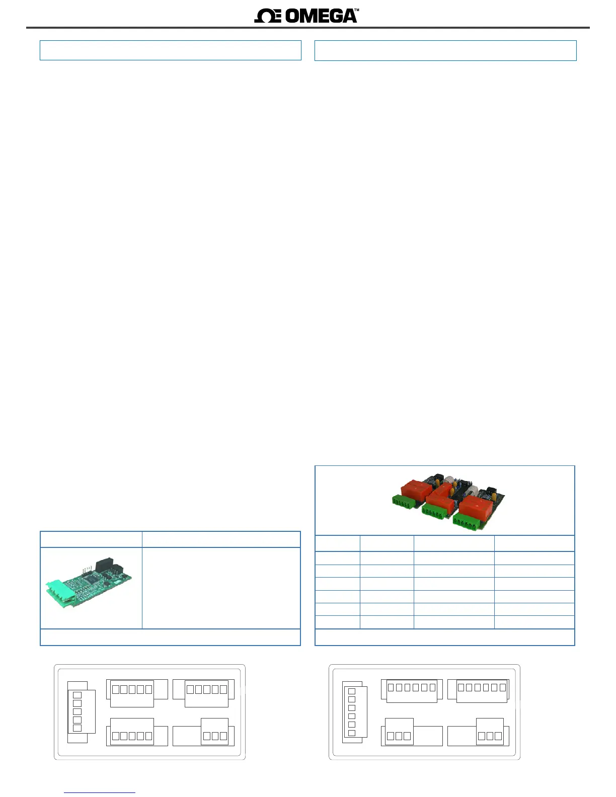
Opon R2, R4, R6
Output type relay (2, 4 and 6 relays)
Relay type 3 contacts (NC, NO, common)
Maximum current 6 A per relay (resisve load)
Maximum voltage* 250 Vac connuous
* terminals approved for 300 V (as per UL1059, groups B and D) and
160 V (as per VDE at CAT-III and polluon degree 3).
Isolaon 2500 Ve
Type of terminal plug-in screw terminal
pitch 5.08 mm
Installaon allowed at ‘Opt.1’
Module R2 occupies Opt.1 (2 relays)
Module R4 occupies Opt.1 and Opt.2 (4 relays)
Module R6 occupies Opt.1, Opt.2 and Opt.3 (6 relays)
Modules R2, R4 and R6 provide 2, 4 and 6 relay outputs, to install in
DPF20 digital panel meters.
Conguraon is performed from the frontal keypad of the meter, by
seng the parameters at the ‘Opt.1’ conguraon menu (not from
the alarm conguraon menu (‘ALr.1’, ‘ALr.2’ o ‘ALr.3’) of the instru-
ment).
The menu allows to congure the setpoint, hysteresis, independent
acvaon and deacvaon delays, and a second setpoint to create
alarm windows.
Only 1 modules R2, R4 or R6 can be installed in a single instrument,
as the are not compable with themselves (2 modules R2 are not ac-
cepted) and are not compable with modules R1, T1 or SSR.
Modules R2, R4 and R6 are isolated against all other instrument cir-
cuits.
Modules R2, R4 and R6 can be ordered pre-installed into a DPF20
digital panel meter, or standalone for delayed installaon, as they do
not require soldering or special conguraon.
2.6 Modules R2, R4 and R6
Rear view DPF20
Power
Opt.2
Opt.1
Opt.3
A B C D E F
Signal
G H I J K L
MNOPQR
Relay Common
Normally Open (NO) Normally Closed (NC)
relay 1 A B C
relay 2 D E F
relay 3 G H I
relay 4 J K L
relay 5 M N O
relay 6 P Q R
Table 17 - Connecon terminals
 Loading...


