Buon ‘LE’
Earth connecon - Although a
terminal is provided for earth
connecon, this connecon is
oponal. The instrument does
not need earth connecon for
correct operaon nor for com-
pliance with the security regu-
laons.
~
~
+
-
8 9 0
Fuse - To comply with security regulaon 61010-1, add to the power
line a protecon fuse acng as disconnecon element, easily acces-
sible to the operator and idened as a protecon device.
Power ‘H’ fuse 250 mA me lag
Power ‘L’ fuse 400 mA me lag
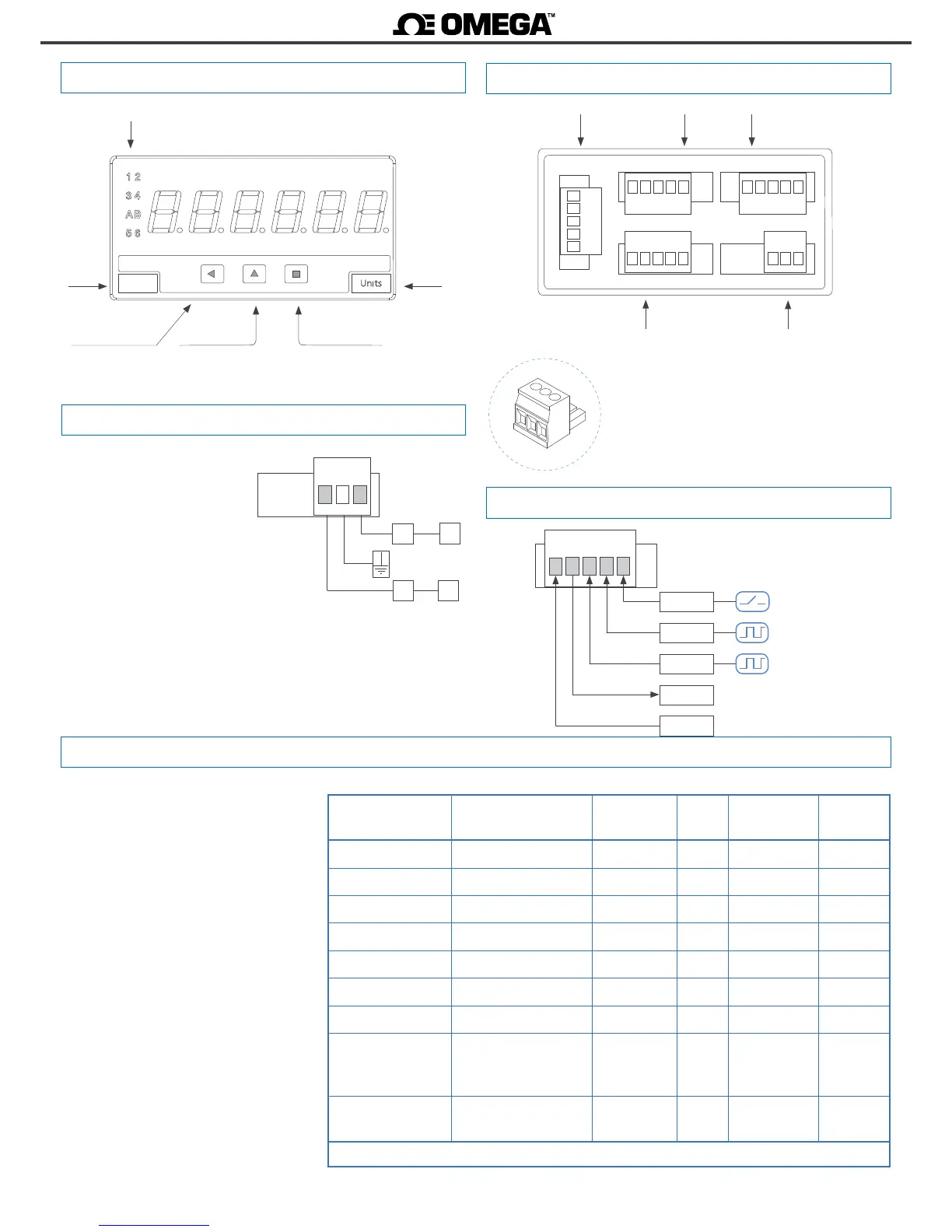
1.7 Power connecons
1.6 Front view
Buon ‘UP’
Logo
Alarms
Units
Buon ‘SQ’
‘Conguraon menu’
(see secon 1.19)
‘Fast access‘
(see secon 1.19.12)
1.8 Sensor conguraon and connecons
Signal
(see secon 1.10)
Opon 1 Opon 2Opon 3
Power
(see secon 1.7)
Detail of the plug-in screw terminals provided with
the instrument. The instrument is provided with all
terminals needed, both male and female.
1.9 Rear view
1.10 Signal connecons
Selecng one of the sensors listed at the
‘SnSr’ menu entry, will congure the sen-
sor parameters to the values indicated in
the table.
The table also indicates the typical con-
necons for each type of sensor. Param-
eters can be manually modied.
Connecons are indicated for a single sen-
sor connected to the channel A. For two
sensors (for inhibion control, quadrature
signal, etc) apply the same connecon cri-
teria also to channel B.
Note : indicated values are typical values.
Check the correct specicaons with your
sensor datasheet and adapt the required
conguraon and connecons as needed.
Sensor Connecons Pulls Vexc. Anrrebound
lter
Trigger
Mechanical contact 0 V channel A pull-up no 100 mSec. 2,5 Vdc
Namur channel A Vexc pull-down 9 Vdc no 3,0 Vdc
NPN 2 wires 0 V channel A pull-up 18 Vdc no 2,5 Vdc
NPN 3 wires 0 V channel A Vexc pull-up 18 Vdc no 2,5 Vdc
PNP 2 wires 0 V channel A pull-down 18 Vdc no 2,5 Vdc
PNP 3 wires 0 V channel A Vexc pull-down 18 Vdc no 2,5 Vdc
Push-pull 0 V channel A Vexc no 18 Vdc no 2,5 Vdc
TTL
CMOS
Pick-up
0 V channel A no 5 Vdc no 2,5 Vdc
AC<30 Vp
Inducve
0 V channel A no no no 0 Vdc
Table 2 - Conguraon and connecons for dierent types of sensors.
Front reset
(see secon 1.19.14)
Vexc.
12345
Canal B
Reset
0 V
Canal A

 Loading...


