Setup and Function
23
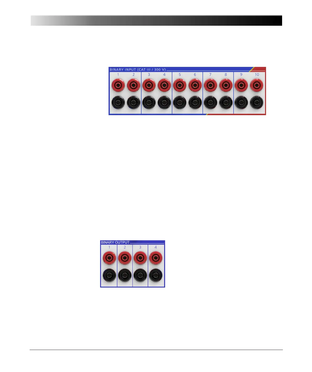
4.1.3 Binary Inputs 1 - 10
Figure 4-4:
Binary inputs 1 - 10
The ten binary inputs are divided into five groups of two, each group
galvanically separated from the others.
The input signals are monitored with a time resolution of 100 µs and then
evaluated in the CPU.
The binary inputs are configured from the Hardware Configuration module
of the OMICRON Test Universe software. When doing so, it can be specified
whether the contacts are potential-sensitive or not. When the contacts are
potential-sensitive, the expected nominal voltage and pick-up threshold can
be set for each binary input.
Moreover, the binary inputs 1 – 10 can be used as counter inputs for input
frequencies up to 3 kHz.
More detailed information about the configuration of the binary inputs can be
found in the OMICRON Test Universe Help.
4.1.4 Binary Output
Figure 4-5:
Binary outputs
Four binary outputs are available for use as
potential-free relay contacts.
More detailed information about the
configuration of the binary outputs can be
found in the OMICRON Test Universe
Help.
 Loading...