Table of Contents
3
TABLE OF CONTENTS
Preface...................................................................................................................... 7
Safety Instructions .................................................................................................. 8
1 Designated Use ............................................................................................ 11
2 Introduction .................................................................................................. 12
3 Operating the CMC 353 ............................................................................... 12
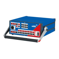
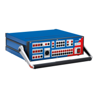
3.1 System Components ..................................................................................................... 12
3.2 Safe Use of the Connecting Cables .............................................................................. 13
3.2.1 Test Lead Adapter for Non-Safety Sockets ....................................................... 13
3.3 Regular Test Leads for Safety Sockets ......................................................................... 14
3.3.1 Terminal adapters.............................................................................................. 14
3.3.2 M4 (0.15") Cable Lug Adapters ......................................................................... 15
3.3.3 M5 (0.20") Cable Lug Adapters ......................................................................... 15
3.4 Starting the Test System ................................................................................................ 16
4 Setup and Function ..................................................................................... 19
4.1 Block Diagram ............................................................................................................... 20
4.1.1 Voltage Output (Voltage Amplifier) .................................................................... 21
4.1.2 Current Output (Current Amplifier)..................................................................... 22
4.1.3 Binary Inputs 1 - 10............................................................................................ 23
4.1.4 Binary Output..................................................................................................... 23
4.1.5 AUX DC (DC Power for Test Objects) ............................................................... 24
4.1.6 CPU ................................................................................................................... 25
4.1.7 Power Supplies (DC-DC)................................................................................... 25
4.2 Signal Generation.......................................................................................................... 25
4.2.1 Accuracy and Signal Quality.............................................................................. 26
5 Connections and Interfaces ........................................................................ 27
5.1 Front Panel Connections ............................................................................................... 27
5.1.1 Generator Combination Socket for VOLTAGE OUTPUT and CURRENT
OUTPUT ............................................................................................................ 30
 Loading...