Do you have a question about the Omicron CMC 353 and is the answer not in the manual?
Important safety notes regarding hazards from voltages and currents.
Guidelines for proper use, manual availability, and personnel training.
Requirements for personnel operating the CMC 353 test set.
Essential procedures for safe operation and handling of the CMC 353.
Instructions for replacing the power fuse on the CMC 353.
Lists the key capabilities and test quantities of the CMC 353.
Lists the necessary components for operating the CMC 353 test system.
Guidelines for safely connecting cables to the CMC 353.
Using adapters to fit standard test leads into non-safety sockets.
Using standard test leads with safety sockets on the CMC 353.
Using terminal adapters to connect test leads to screw-clamp terminals.
Connecting test leads to M4 screw-clamp terminals.
Connecting test leads to M5 screw-clamp terminals.
Steps to connect and start the CMC 353 test system with a computer.
Overview of the CMC 353 internal signal flow and connections.
Details on the voltage outputs, ranges, and protection mechanisms.
Details on the current outputs, protection, and amplifier type.
Description of the ten binary inputs and their configuration.
Description of the four binary outputs and their functionality.
Functionality and safety of the auxiliary DC power output.
Tasks performed by the Central Processing Unit of the CMC 353.
Information on the DC-DC power supply implementation.
How the CMC 353 generates test signals using digital signal processing.
Details on the precision, drift, and calibration of the CMC 353.
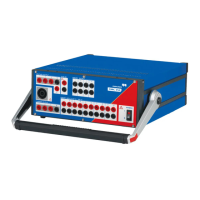
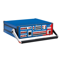
Overview of all connectors and controls on the front panel.
Visual representation of binary input/output circuits.
Circuit diagrams of current and voltage output stages.
Description and warnings for the combination socket.
Pin assignment for the generator combination socket.
Details about the socket's manufacturer and part number.
Details on the Ethernet ports for network communication and control.
Function of the '!' button for emergency recovery.
Functions of the Associate button for computer association and IP reset.
Explanation of the status LEDs for troubleshooting.
Configuration of network settings for communication.
Firewall configuration for network communication.
Guidance for troubleshooting network connectivity issues.
Details on the external interface for binary outputs and counter inputs.
Description of low-level outputs for external amplifiers.
Information on the protective features of low-level outputs.
General conditions for guaranteed technical specifications.
Technical data for the main power supply connection and fuse.
Electrical insulation specifications for safety.
General specifications for analog and LL outputs.
Performance data for extended frequency range operation.
Detailed technical specifications for all current output configurations.
Power output curves for three-phase operation.
Power output curves for single-phase operation.
Compliance voltage curves related to overload detection.
How current output is affected by frequency.
Graphs showing continuous output power vs. current.
Duty cycle examples for discontinuous operation.
Detailed technical specifications for all voltage output configurations.
Graphical representation of power output vs. voltage for three-phase.
Power output diagrams for single-phase L-N and L-L operation.
How mains supply voltage affects output power.
Limits when using current and voltage amplifiers together.
Details on LL outputs for connecting external amplifiers.
Technical data for the SELV "LL out" outputs.
Details on transistor binary outputs via the external interface.
Circuit diagram for external interface binary outputs.
Specifications for the 4 binary output relays.
Technical data for the auxiliary DC power supply.
General data and potential-sensing operation for binary inputs.
Specific data for binary inputs in potential-sensing mode.
Specific data for binary inputs in potential-free mode.
How the system handles bouncing input signals.
Technical details for high-frequency counter inputs.
Operating and storage conditions for temperature and humidity.
Test standards for vibration and shock resistance.
Adherence to CE directives for EMC and low voltage.
Emission and immunity standards for electromagnetic compatibility.
List of relevant safety standards and certifications.
Crucial safety guidelines for high current operation.
Methods for increasing output power using single-phase operation.
Details on the 1x32A high burden mode with L-L connection.
Details on the 1x64A high current mode with LL-LN connection.
Operation modes for single-phase voltage output.
Connecting external amplifiers to expand capabilities.
Systematic steps to diagnose and resolve operational problems.
Common errors, their causes, and suggested solutions.
Diagnosis and prevention of thermal shutdown issues.
Description of external amplifiers for CMC 353.
Description of the CMControl-3 front panel control device.
Details on the CMGPS synchronization unit for time synchronization.
Information on the CMIRIG-B interface box for time reference.
Items included in the standard delivery package.
Details on the optional wiring accessory package.
Copyright notices for OMICRON Bootloader software components.