Technical Data
59
Table 6-18:
Data for potential-free
operation
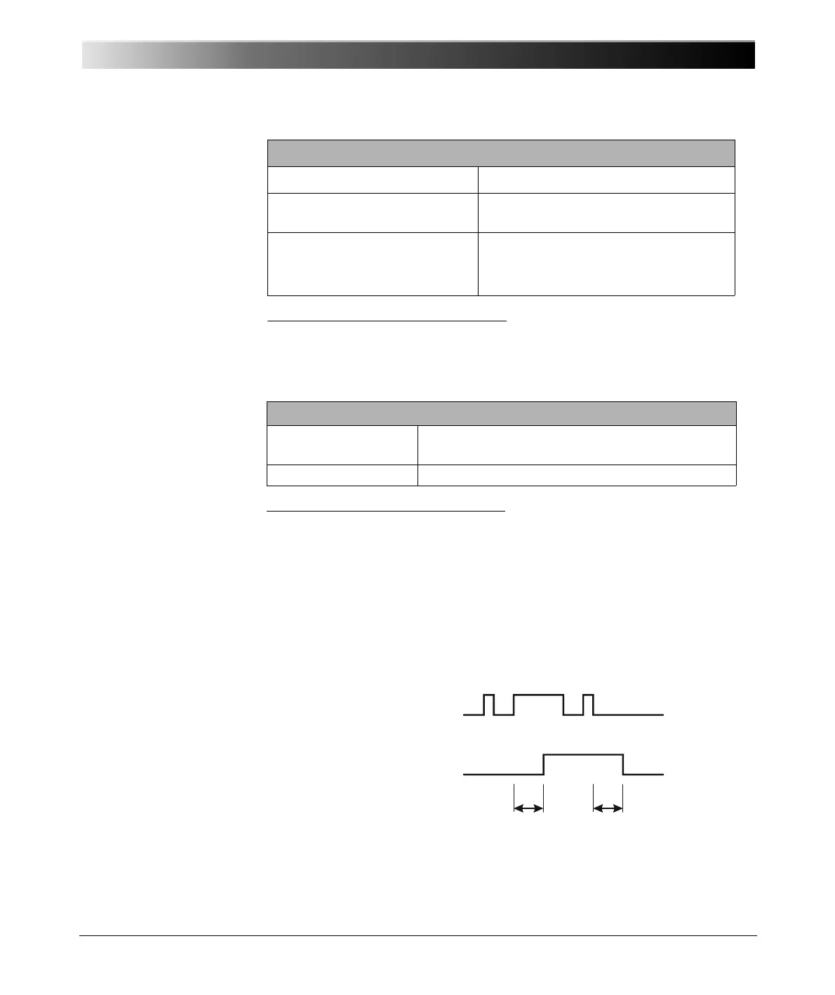
Deglitching input signals
In order to suppress short spurious pulses a deglitching algorithm could be
configured. The deglitch process results in an additional dead time and
introduces a signal delay. In order to be detected as a valid signal level, the
level of an input signal must have a constant value at least during the
deglitch time. The figure below illustrates the deglitch function.
Figure 6-14:
Signal curve, deglitching
input signals
Threshold voltage accuracy
1
5% of rd. + 0.5% of rg.
Threshold voltage hysteresis Range I: typ. 60 mV
Range II: typ. 900 mV
Input impedance
2
Threshold 0...20V
Threshold 20...300V
210 k
Ω
135 kΩ
1
Applies to positive voltage signal edge; value shown in % of reading (rd.) + % of upper range
value (rg.)
2
Refer to figure 5-2, "Simplified circuit diagrams of binary inputs and outputs" on page 28.
Data for Potential-Sensing Operation
Data for Potential-Free Operation
1
1
Refer to figure 5-2, "Simplified circuit diagrams of binary inputs and outputs" on page 28.
Trigger criteria
Logical 0: R > 100 k
Ω
Logical 1: R < 10 kΩ
Input impedance
216 k
Ω
Input signal
Input signal deglitched
T
deglitch
T
deglitch
 Loading...