38
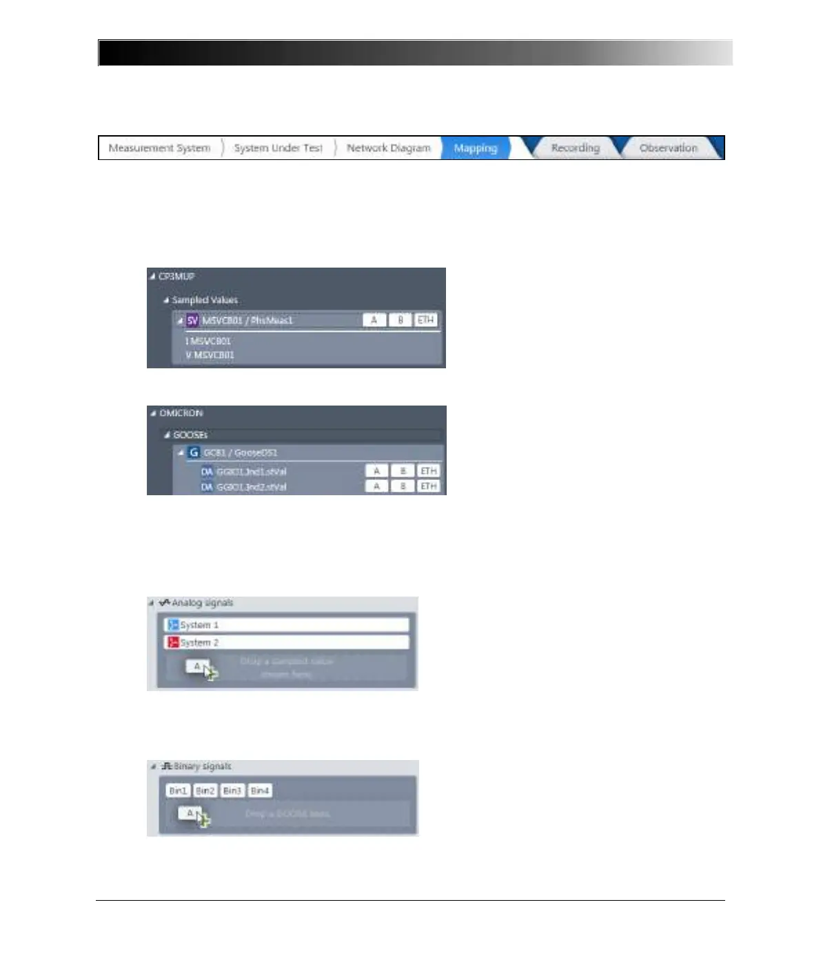
5.1.5 Mapping
In Mapping, you can map voltages, currents, and binary values, which are encapsulated in Sampled
Values and GOOSE as well as hard-wired inputs and phase systems to specific devices. This way,
you build up a signal pool for every device.
Mapping signals to a device
1. In the Navigation pane, expand “IED” > Sampled Values until you see ports A, B, ETH.
You get the currents and voltages of every “IED”.
2. In the Navigation pane, expand “IED” > GOOSE until you see ports A, B, ETH.
You get the binary signals of every “IED”.
Note: The device needs to know on which port (A, B, or ETH) the GOOSE or Sampled Value
streams can be read.
3. In the Devices section, choose the device.
4. From the Navigation pane, drag the port of the Sampled Value that you want to map to the
Analog signals.
The voltage and current (phase system) appear. You can now combine a voltage and current
to generate a power system.
5. From the Navigation pane, drag the port of the GOOSE data attribute (DA) that you want to
map to the Binary signals.
Note: Each device can hold up to three Sampled Value streams.