EasyManuals Logo

Omicron DANEO 400 User Manual

Omicron DANEO 400
80 pages
To Next Page IconTo Next Page
To Previous Page IconTo Previous Page
Page #61 background imageLoading...
Page #61 background image
DANEO 400 hardware
61
7 DANEO 400 hardware
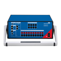
The DANEO 400 hardware interface is located at the front and rear panels of the device.
7.1 Front panel
1
2
3
4
5
6
7
8
9
10
11
12
13
1
Ethernet network process ports
2
USB 3.0 device port to connect external storage devices
3
EtherCAT output ports for extension devices, such as binary I/O extension box, capable of
powering devices with PoE+ (~25 W each port)
4
Binary outputs
5
Power-status LED
6
Ethernet network control port
7
USB 2.0 host control port
8
General device status LEDs
9
Reset button
10
EtherCAT communication status LEDs
11
Analog/binary inputs
12
Power switch
13
Handle

Table of Contents

Questions and Answers:

Question and Answer IconNeed help?

Do you have a question about the Omicron DANEO 400 and is the answer not in the manual?

Omicron DANEO 400 Specifications

General IconGeneral
BrandOmicron
ModelDANEO 400
CategoryMeasuring Instruments
LanguageEnglish

Related product manuals