2 Installation and connection
2-1 Installation
■ Rack mounting procedure
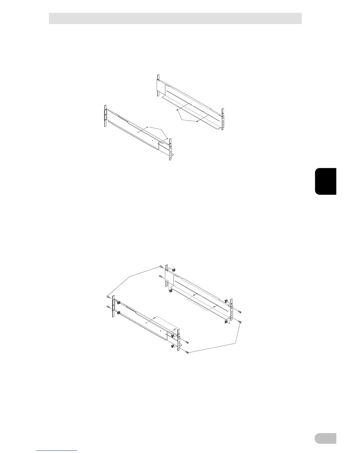
1. Insert the 4 included rail length fixing screws (M4) and half-tighten them to hold the
front and rear rack rails in place. (1 There are 2 types of the front rack rail; left (L) and
right (R). The rear rack rails are same.
2. Adjust the length of support angles to suit the server rack, and then securely tighten the
screws that were half-tightened in step 1. (2
3. For EIA standard-compliant installation, use the 8 included EIA rack fixing nuts (M5)
and 8 EIA/JIS rack fixing screws (M5) to securely fasten the front (the side displaying
“L” or “R”) and the back of the support angles to the server rack. (3 The screw holes
are located at the top and bottom for both front and rear.
For JIS standards, use a total of 6 included screws to fix the rack; 1 JIS rack fixing
flat-head screw (M5) at a front position of the each of right and left support angles, 2
EIA/JIS rack fixing screws (M5) at 2 rear positions. (3 The screw hole position for the
front is at the second screw hole from the top, the rear is at the second screw hole from
the bottom.