3-45
3 Configuration Software
CJ-series PROFIBUS Master Unit Operation Manual for NJ-series CPU Unit (W509)
3-3 Generic Slave Device DTM
3
3-3-1 Configuration User Interface
Max. Alarm PDU Length
This parameter defines the maximum size of an Alarm message sent from the slave device to the
PROFIBUS DP-V1 Master Unit. The Master Unit uses this number to reserve buffers to handle the
alarms. The maximum alarm message size ranges from 4 bytes to 63 bytes.
Alarms
The Alarms box defines the types of alarms the slave device will report as well as the alarm handling
capacity of the master device. The settings in this box are conveyed to the slave device through the
Set_Prm message sent by the PROFIBUS DP-V1 Master Unit.
Extra Alarm SAP
For acyclic data exchange between a PROFIBUS DP-V1 Master Unit (Class 1) and a PROFIBUS
DP-V1 slave device one specific SAP (Service Access Point, the PROFIBUS definition for a mes-
sage identifier) is defined by the PROFIBUS DP Extension standard. By default SAP 51 is used for
acyclic data exchange with the PROFIBUS DP-V1 Master Unit (Class 1).
For efficiency reasons however, acknowledgement of alarms can be performed using a different,
dedicated SAP or message identifier; SAP50. This will allow other acyclic communication (e.g. re-
parameterization of the slave device) to continue without interference.
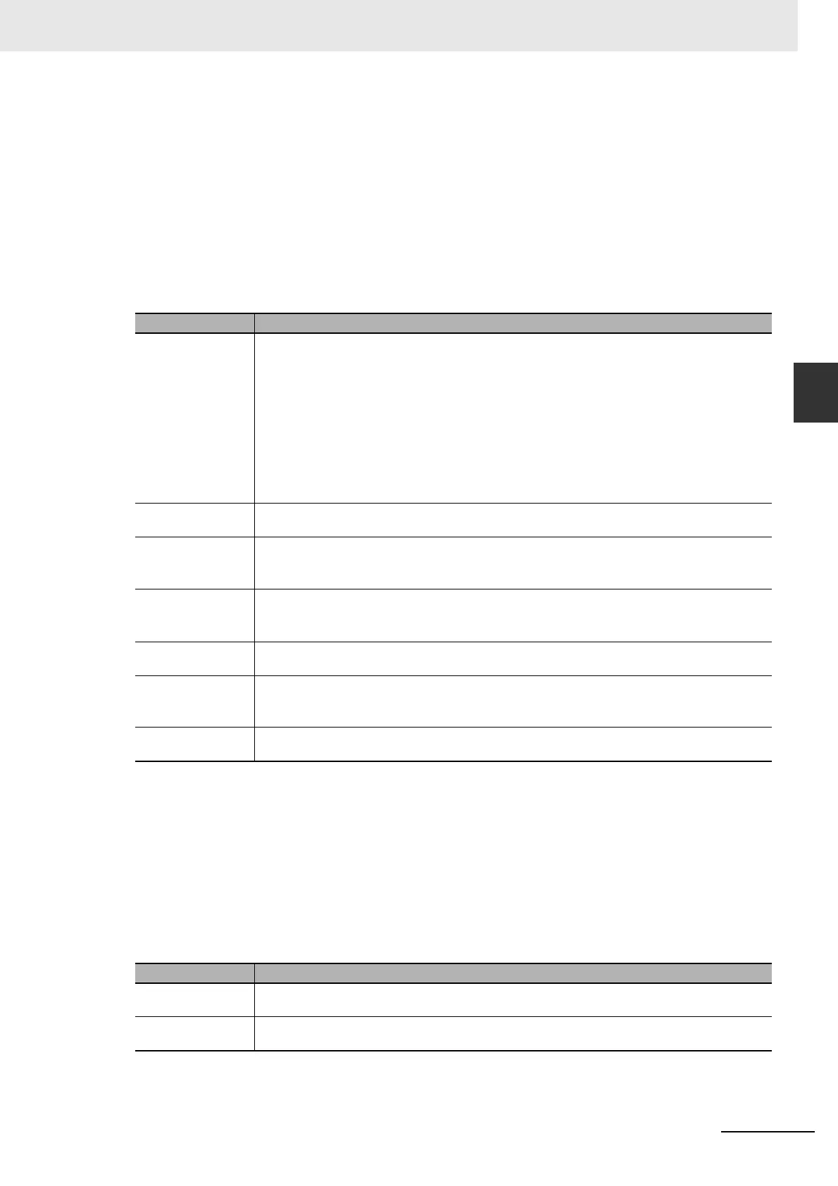
Control Description
Alarm mode The Alarm mode indicates to the slave device the amount of alarms the PROFIBUS DP-V1 Master
Unit can process simultaneously. The following standard selections are available:
• 1 alarm of each selected type
• 2 alarms in total
• 4 alarms in total
• 8 alarms in total
• 12 alarms in total
• 16 alarms in total
• 24 alarms in total
• 32 alarms in total
Pull Plug alarm When set, this checkbox enables the signaling of a pull/plug alarm type, i.e. the removal/insertion of a
hardware I/O module.
Process alarm When set, this checkbox enables the signaling of a process alarm type, i.e. an alarm related to the
process connected to the I/O.
Example: Upper Limit exceeded alarm.
Diagnostic alarm When set, this checkbox enables the signaling of a diagnostic alarm, i.e. an alarm related to the func-
tioning of a specific I/O module in a slot.
Example: Short circuit detected.
Manufacturer spe-
cific alarm
When set, this checkbox enables the signaling of a Manufacturer specific alarm.
Status alarm When set, this checkbox enables the signaling of a Status alarm, i.e. an alarm related to an internal
state change in a module.
Example: Change to Run state, Stop state.
Update alarm When set, this checkbox enables the signaling of an Update alarm, i.e. an alarm indicating a change in
the parameters related to a specific module, either by local or remote access.
Control Description
Alarm acknowledge
via SAP 51
When selected, the PROFIBUS DP-V1 Master Unit will acknowledge each received alarm using SAP
51 message identifier (default).
Alarm acknowledge
via SAP 50
When selected, the PROFIBUS DP-V1 Master Unit will acknowledge each received alarm using SAP
50 message identifier.

 Loading...


