2 Nomenclature and Installation
2-2
CJ-series PROFIBUS Master Unit Operation Manual for NJ-series CPU Unit (W509)
2-1 Unit Components
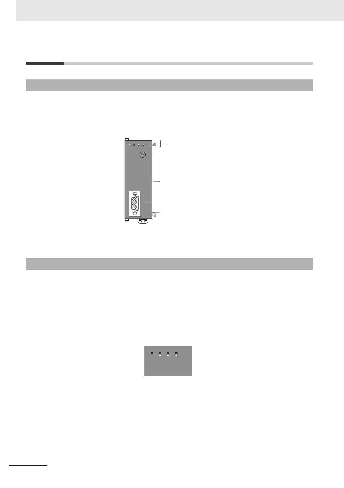
The illustration below shows the Status indicators, the Unit number selector switch and a 9-pin female
sub-D connector on the front side of the CJ1W-PRM21 Unit. Each of these components are explained
in the following sections.
The CJ1W-PRM21 PROFIBUS Master Units are each fitted with seven LEDs to indicate the operational
mode and status of the Unit and the PROFIBUS network.
2-1-1 Nomenclature
2-1-2 Indicators
Indicators
Unit number switch
This switch sets the Unit Number of the
PROFIBUS DP Master Unit as a one-digit
hexadecimal number
PROFIBUS DP Connector
9-Pin Sub-D, female connector, #4/40 UNC thread
Connect the PROFIBUS DP network cable to this
connector. Termination must be provided with the
cable connector
CJ1W-PRM21
ERC
RUN
BF
PRM21
COMM
BST
ERH
PRM
NO.
UNIT
0
1
2
3
4
5
6
7
8
9
A
B
C
D
E
F
BUS
CJ1W-PRM21
ERC
RUN
BF
PRM21
COMM
BST
ERH
PRM

 Loading...


