2 Nomenclature and Installation
2-4
CJ-series PROFIBUS Master Unit Operation Manual for NJ-series CPU Unit (W509)
3
Turn ON the power again.
Note If the unit number is being set for the first time or changed, then an I/O table must be created
for the CPU.
Precautions for Correct UsePrecautions for Correct Use
• Use a small flat-blade screwdriver to turn the rotary switches; be careful not to damage the
switch.
• Always turn OFF the Controller before you change the unit number setting.
If the unit number is the same as one set on another CPU Bus Unit connected to the same CPU
Unit, a duplicate number error will occur in the CPU Unit and it won't be possible to start up the
PROFIBUS network.
Unit Number and CPU Bus Unit Word Allocations
With NJ-series controller units, words can be allocated in the CIO Area and the DM Area via Device
Variables. The PROFIBUS Master Unit uses these words for receiving control data from the CPU
Unit and for notifying the CPU Unit of PROFIBUS Master Unit and communications status. The word
addresses in the allocated areas for the CPU Bus Unit are important when creating the user pro-
gram for using the PROFIBUS Master Unit. This must be considered when setting the unit number.
The CIO and DM Word allocations are discussed in detail in section 4-1 Data Exchange with the
CPU Unit
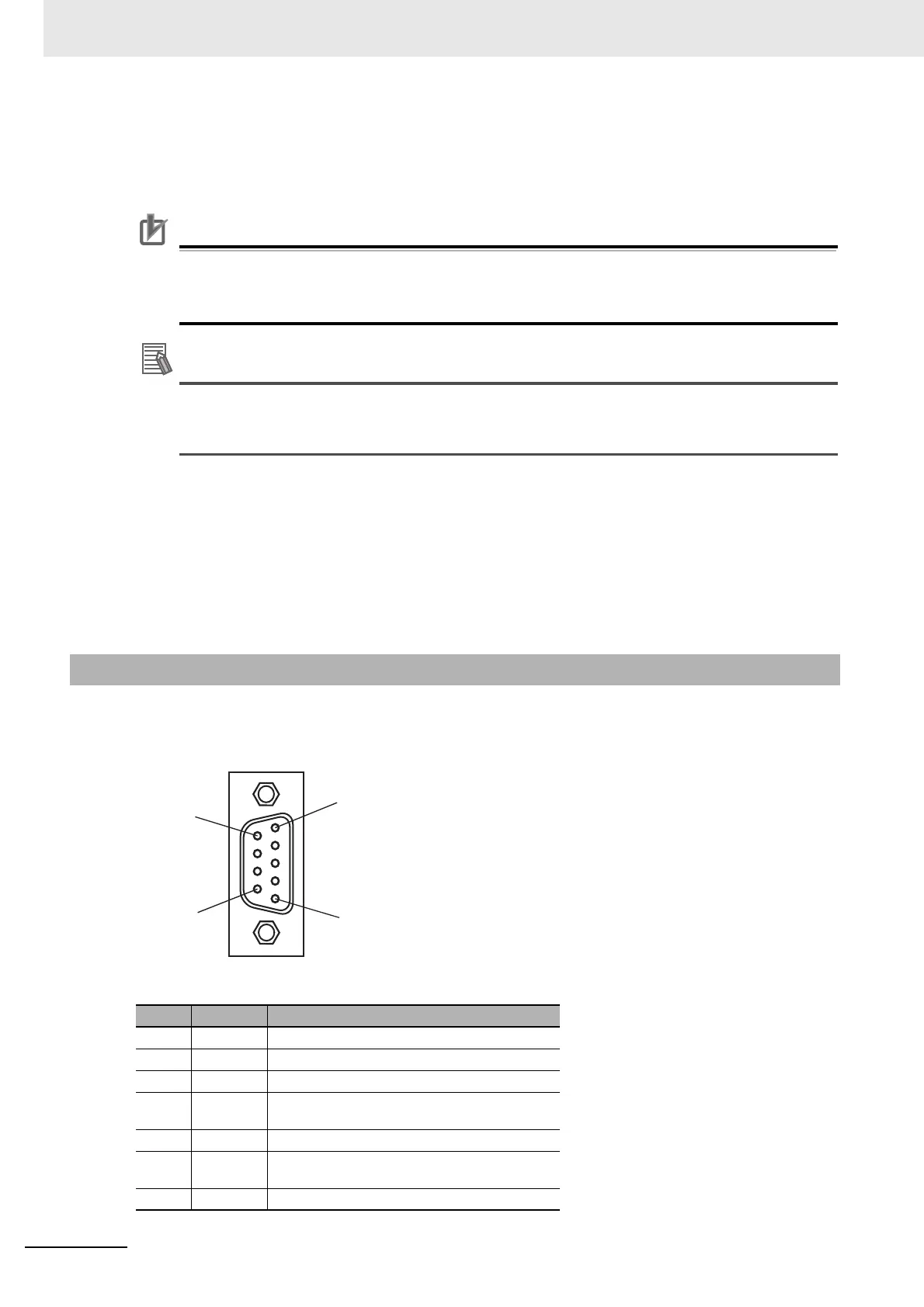
The PROFIBUS connector on the font of the Unit is a 9-pin female sub-D connector, as recommended
by the PROFIBUS standard EN 50170.
2-1-4 PROFIBUS Connector
Pin No. Signal Description
1 Shield Shield/protective ground
2--
3 RxD/TxD-P Receive/Transmit data - plus (B wire)
4 RTS Control signal for repeaters (direction control)
(TTL)
5 DGND Data ground (reference potential for VP)
6 VP Supply voltage of the terminator resistance (5
VDC)
7--
5
9
1
6
 Loading...


