5 Operation
5-26
CJ-series PROFIBUS Master Unit Operation Manual for NJ-series CPU Unit (W509)
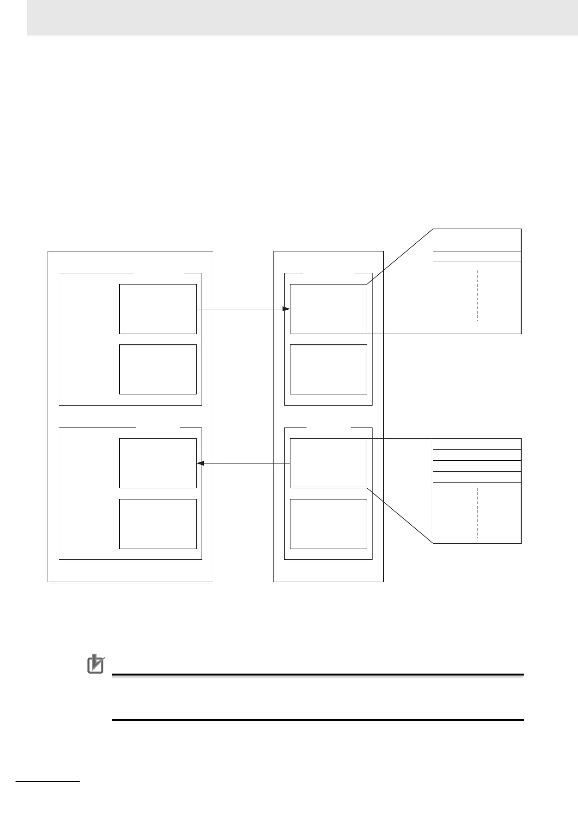
• I/O modules per slave device, are mapped in the order in which they were selected, when set-
ting up the slave device.
Furthermore, Input area 1 is by default mapped to CIO 3300, whereas Output area 1 is by default
mapped to CIO 3200.
The default mapping algorithm is illustrated in the figure below, with the following configuration:
• Slave device 1: One input/output module, one output modules.
• Slave device 2: One input module.
• Slave device 3: One output module.
• Slave device 4: Two input modules.
Note 1 The end address of each Input/Output area in the CPU memory, depends on the size of the
allocated I/O data.
2 If more than 100 words of input or output have been configured for the slave, overlap of
memory areas will occur in the CPU if default I/O mapping is used as shown above.
Precautions for Correct UsePrecautions for Correct Use
The default mapping of areas on to the CPU memory is the same default mapping as used in the
CJ1W-DRM21 Devicenet Master/Slave Unit. Care should be taken to avoid data overlap if such
a Unit is part of the same CPU system as the CJ1W-PRM21 PROFIBUS Master Unit.
The CJ1W-PRM21 PROFIBUS Master Unit, will assemble the correct PROFIBUS data messages
from the storage order in the Input and Output memory areas.
Out put area
Out put area 1
Out put area 2
PROFIBUS Master Unit
Input area 1
Input area 2
Input area
Slave1:Module1
Slave1:Module2
Slave1:Module1
Slave2:Module1
Slave4:Module1
Slave4:Module2
Slave3:Module1
Out put area
Out put area 1
Out put area 2
CPU Unit
Input area 1
Input area 2
Input area
CIO 3200
CIO 3400
CIO 3300
CIO 3500

 Loading...


