5-39
5 Operation
CJ-series PROFIBUS Master Unit Operation Manual for NJ-series CPU Unit (W509)
5-5 I/O Communication Characteristics
5
5-5-5 I/O Response Time
T
IN
Slave device Input TRUE (FALSE) delay.
T
PB,Cyc
PROFIBUS I/O data exchange cycle time (See Appendix A, Bus Parameters)
T
M,Proc
I/O Processing time in the Master Unit.
T
M,Rrf
Master request cyclic refresh until actual start of cyclic refresh.
T
CPU,Cyc
CPU cycle time.
T
CPU,Rf
CPU cyclic refresh time.
T
OUT
Slave device Output TRUE (FALSE) delay.
The total I/O response time is the sum of all components:
T
IO
= T
IN
+ 4*T
PB,Cyc
+ 2*T
M,Proc
+ T
M,Rrf
+ 2*T
CPU,Cyc
+ T
CPU,Rf
+ T
OUT
Note The calculation assumes the presence of only one Master Unit on the PROFIBUS network.
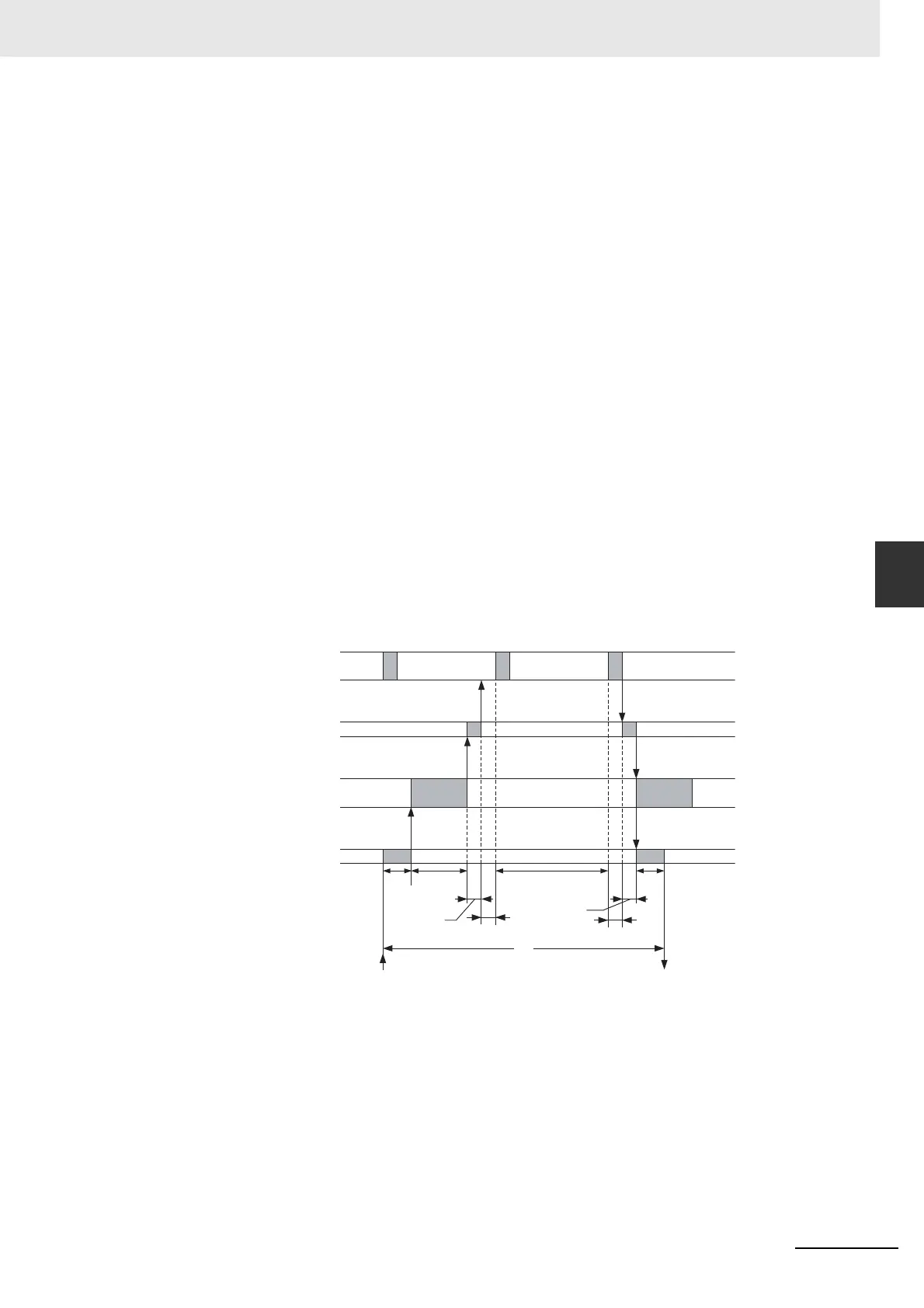
Minimum I/O Response Time
The minimum response time, i.e. the time from an input on a slave device being set to the time the
output on the same slave device is set is calculated, based on the figure below. The following
assumptions are made:
The slave device is the first one in the PROFIBUS I/O data exchange.
The input data is available right before the internally generated cyclic refresh request is set. In this
case, a complete cyclic refresh will take place (See section 5-5-4 Exchanging I/O Data Over PROFI-
BUS).
T
IN
Slave device Input TRUE (FALSE) delay.
T
PB,Cyc
PROFIBUS I/O data exchange cycle time (See Appendix A, Bus Parameters)
T
M,Proc
I/O Processing time in the Master Unit.
T
M,Rrf
Master request cyclic refresh until actual start of cyclic refresh.
T
CPU,Cyc
CPU cycle time.
T
CPU,Rf
CPU cyclic refresh cycle time.
T
OUT
Slave device Output TRUE (FALSE) delay.
CPU Cycle
PROFIBUS Cycle
Master Unit processing
Slave I/O data refresh
T
CPU,Rf
T
I/O
T
IN
T
PB,Cyc
T
CPU,Cyc
T
OUT
T
M,proc
T
M,proc
TRUE TRUE
T
M,Rrf
Instruction
Execution
Instruction
Execution
Instruction
Execution

 Loading...


