Appendices
A-10
CJ-series PROFIBUS Master Unit Operation Manual for NJ-series CPU Unit (W509)
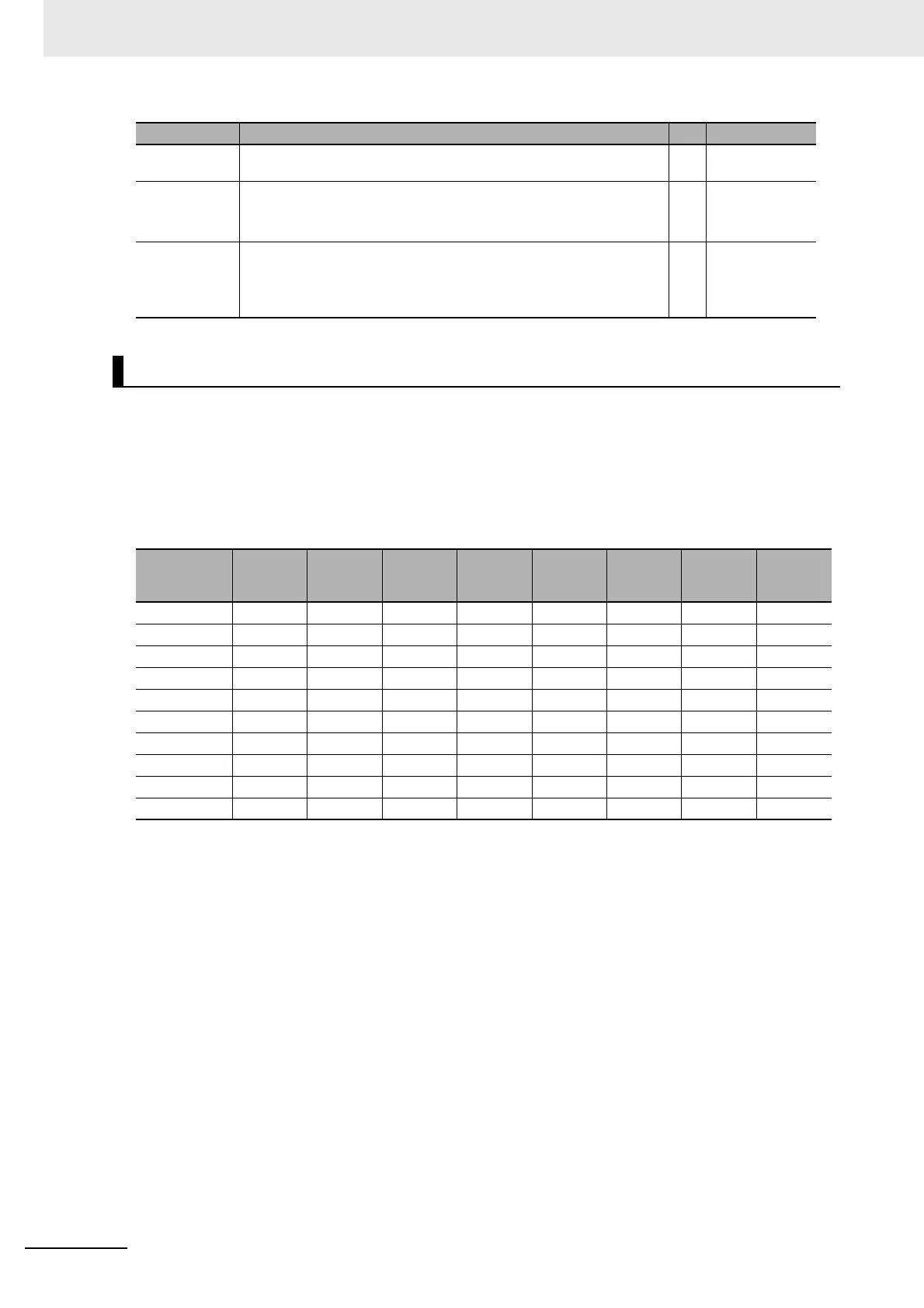
The bus parameters defined in the previous paragraph are used to configure the PROFIBUS DP
hardware interface and to calculate the cycle time for I/O data exchange as well as the watchdog
value. Most of the parameters, set in the Bus Parameter Tab are directly transferred to the interface
hardware registers. The table below, lists these parameters, along with their default value for the
available baud rates. These values are also the minimum values for each parameter at a given baud
rate.
The parameters to calculate are:
• Min. Slave Interval (t
BIT
)
• Target Rotation Time (t
BIT
)
• Watchdog timeout (ms)
• Data Control Time (ms)
These four values depend on the number of slave devices allocated to the PROFIBUS Master Unit,
the number of I/O bytes each of the slave devices will exchange with the Master Unit, and how many
other Master Units are on the PROFIBUS network at the same time. Furthermore, the Unit will
require additional time to process the PROFIBUS I/O data and exchange this with the CPU.
Based on this, the Min. Slave Interval value for one Master Unit can be calculated as follows:
Min. Slave Interval = A
1
+ (B
1
* slave devices) + (C
1
* bytes to transfer) +
(bits per s)*((A
2
* slave devices) + B
2
* modules) + (C
2
* Words to exchange)[1]
in which: A
1
, B
1
, C
1
are constants (
t
BIT
) determining the PROFIBUS DP cycle time on the bus,
Poll Timeout The maximum time interval that this master device may need for the execu-
tion of a master-master function.
ms No
Data Control
Time
The cycle time in which the master updates its Data Transfer List, in which it
keeps an overview of all slave states. Data Control Time is based on the
Watchdog time T
WD
: Data Control Time = 7*T
WD
.
ms No
Watchdog Con-
trol
The Watchdog Control Time defines the time for a slave device to set its out-
puts to a fail-safe state, if during that time no communication between the
Master device and that slave device was detected. The Watchdog is auto-
matically set for all configured slaves, based on the value of T
TR
.
ms Yes
Determining the Bus Parameters
Baud rate
[kBits/s]
T
QUI
[t
BIT]
T
SET
[t
BIT]
T
SL
[t
BIT
]
G
Retry
Limit
Poll Time-
out
[ms]
min T
SDR
[t
BIT
]
max T
SDR
[t
BIT
]
9.6 0 1 100 1 1 10 11 60
19.2 0 1 100 1 1 10 11 60
45.45 0 95 640 1 1 10 11 400
93.75 0 1 100 1 1 10 11 60
187.5 0 1 100 1 1 10 11 60
500 0 1 200 1 1 10 11 100
1500 0 1 300 1 1 10 11 150
3000 3 4 400 1 2 10 11 250
6000 6 8 600 1 3 10 11 450
12000 9 43 1000 1 4 10 11 1600
Item Description Unit Editable by User

 Loading...


