1-13
1 Features and System Configuration
CJ-series PROFIBUS Master Unit Operation Manual for NJ-series CPU Unit (W509)
1-2 PROFIBUS Master Unit
1
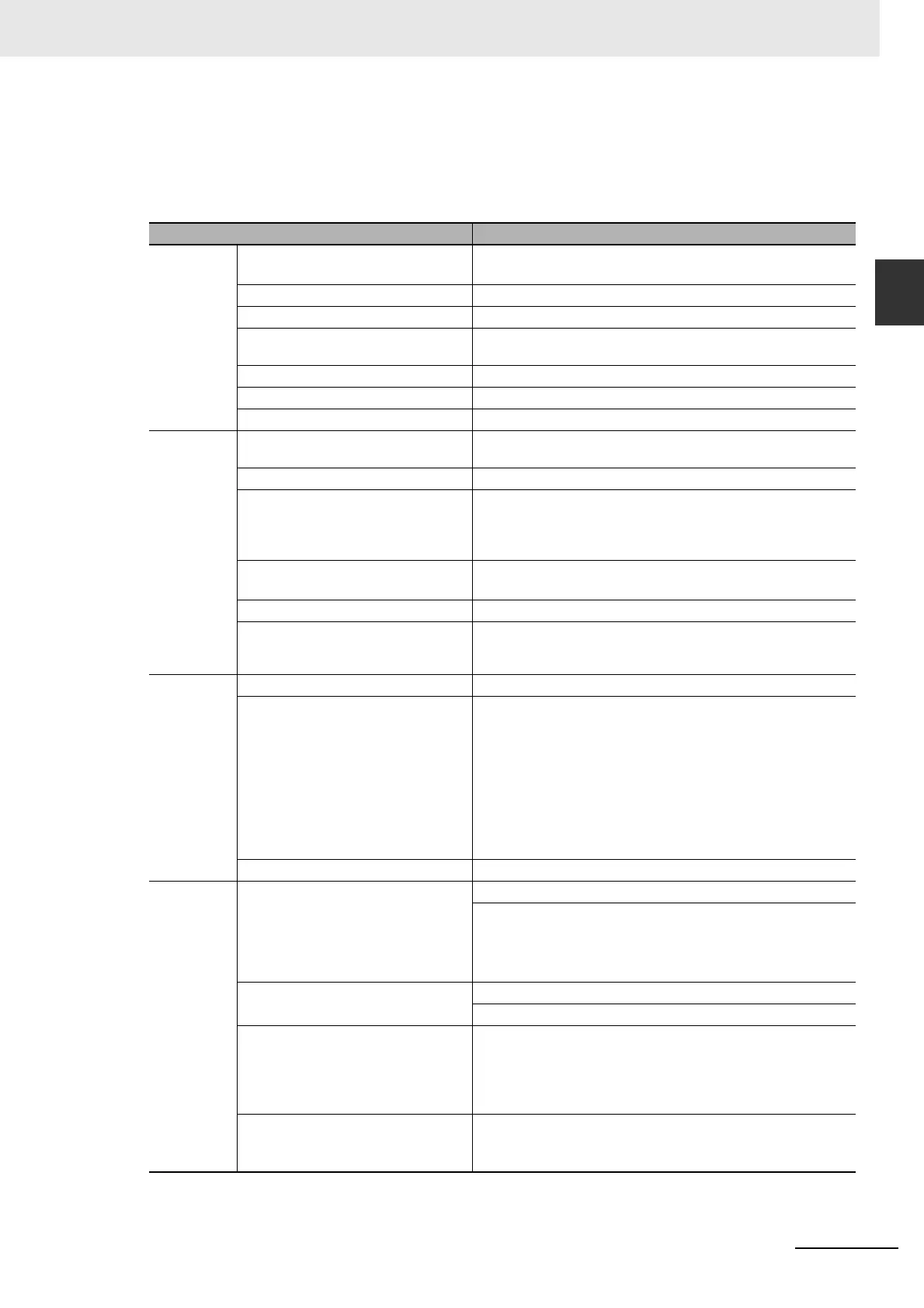
1-2-2 Specifications
General Specifications
General specifications of the CJ-series PROFIBUS Master Units conform to the general specifica-
tions for the NJ-series Controller Units.
Item Specification
Installation Mounting position • CPU Rack,
• Expansion Rack
Unit classification CPU Bus Unit
Applicable unit numbers 0 to F (Hex)
Maximum number of Units per NJ-series
Controller Unit
16
Current consumption 400 mA max at 5 VDC
Dimensions (W x H x D) 31 x 90 x 65 mm
Weight 100g (typical)
Environment Ambient temperatures Operating temperature: 0 to 55C
Storage temperature: –20 to 75C
Ambient operating humidity 10% to 90% (with no condensation)
Vibration resistance Conforms to IEC60068-2-6, test Fc. 10 to 54.8Hz, 0.25-mm ampli-
tude, 54.8 to 300Hz, acceleration: 29.4 m/s
2
in X, Y, and Z direc-
tions for 120 minutes each. (Total time: 12 linear sweeps x 10
minutes / sweep = 120 minutes)
Shock resistance
Conforms to IEC60068-2-27, test Ea. 196 m/s
2
three times each in
X, Y, and Z directions
Dielectric strength 600 VAC (between isolated circuits)
Conformance to EMC and Electrical
safety standards
EN61000-6-2: 2001
EN61000-6-4: 2001/CISPR11
EN61131-2:1994+a12:2000
Front Case Settings Unit Number rotary switch, range: 0 to F (Hex)
Indicators 7 LEDs, indicating Unit status and PROFIBUS status:
Unit status: RUN (Green indicator)
ERC (Red indicator)
Host CPU status: ERH (Red indicator)
Configuration status: PRM (Green indicator)
PROFIBUS status: BST (Green indicator)
COMM (Green indicator)
BF (Red indicator)
PROFIBUS Connector 9-pin sub-D female connector (#4/40 UNC thread)
Memory Area
Allocation
CIO Area words allocated for the CPU
Bus Unit
Fixed allocation of 25 words per Unit.
CIO words provide:
• 2 words for software switches
• 1 word for the Global-Control
• 21 words for the Unit and Slave statuses
DM Area words allocated for the CPU
Bus Unit.
Fixed allocation of 100 words per Unit.
DM Area allocated to the Unit is reserved for future use.
I/O Data allocations Maximum total size: 7168 words
I/O Data can be allocated to up to 2 input areas and 2 output areas.
Input and output areas can be mapped to CIO, DM, WR, and HR
Areas, as well as EM banks. Mapping must be defined through con-
figurator.
PROFIBUS DP-V1 status flags DPV1 Connection/Abort status flags: 16 words.
The status flags can be mapped to CIO, DM, WR, and HR Areas, as
well as EM banks. Mapping must be defined through configurator.