!
68
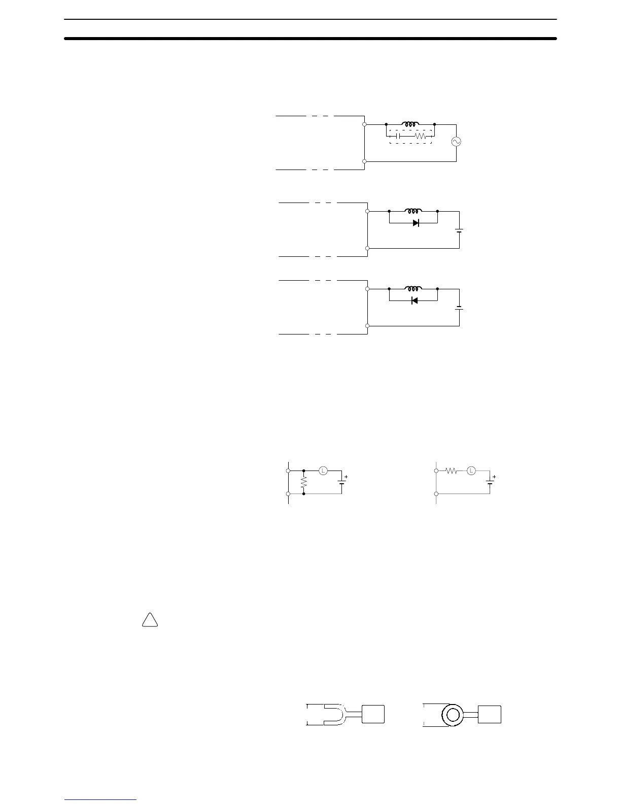
Inductive Loads
When connecting an inductive load to an input, connect a surge protector or
diode in parallel with the load.
The surge protector’s components should have the following ratings:
OUT
COM
CPM1A
Surge protector
Relay Output
OUT
COM
CPM1A
Diode
Relay Output
Transistor Output
(Sinking Output)
OUT
COM
CPM1A
Diode
Relay Output
Transistor Output
(Sourcing Out-
put)
The diode should satisfy the following requirements:
Peak reverse-breakdown voltage must be at least 3 times the load voltage.
Average rectified current must be 1 A.
Inrush Current Considerations
When switching a load with a high inrush current in the CPM1A relay output or
transistor output model, such as an incandescent lamp, suppress the inrush cur-
rent as shown below.
OUT
COM
R
OUT
COM
R
Countermeasure 1
Providing a dark current of
approx. one-third of the rated
value through an incandescent
lamp
Countermeasure 2
Providing a limiting resistor
Fuse Insertion
The CPM1A with transistor output may burn if the load is short-circuited, there-
fore, insert a protective fuse in series to the load.
Crimp Connectors
Caution Always use crimp connectors for the CPM1A’s power lines and I/O lines or else
use a solid wire (instead of a stranded wire). Do not connect bare stranded wires
directly to terminals. Bare stranded wires connected directly to the terminal can
cause a fire.
Use M3 terminal screws and tighten the screws securely (0.5 N m).
6.2 mm max. 6.2 mm max.
Fork terminal Ring terminal
The recommended wire size for solid wires is 0.4 to 1.2 mm (AWG26 to AWG18).
Wiring and Connections
Section 3-4