102
Procedures Section 3-2
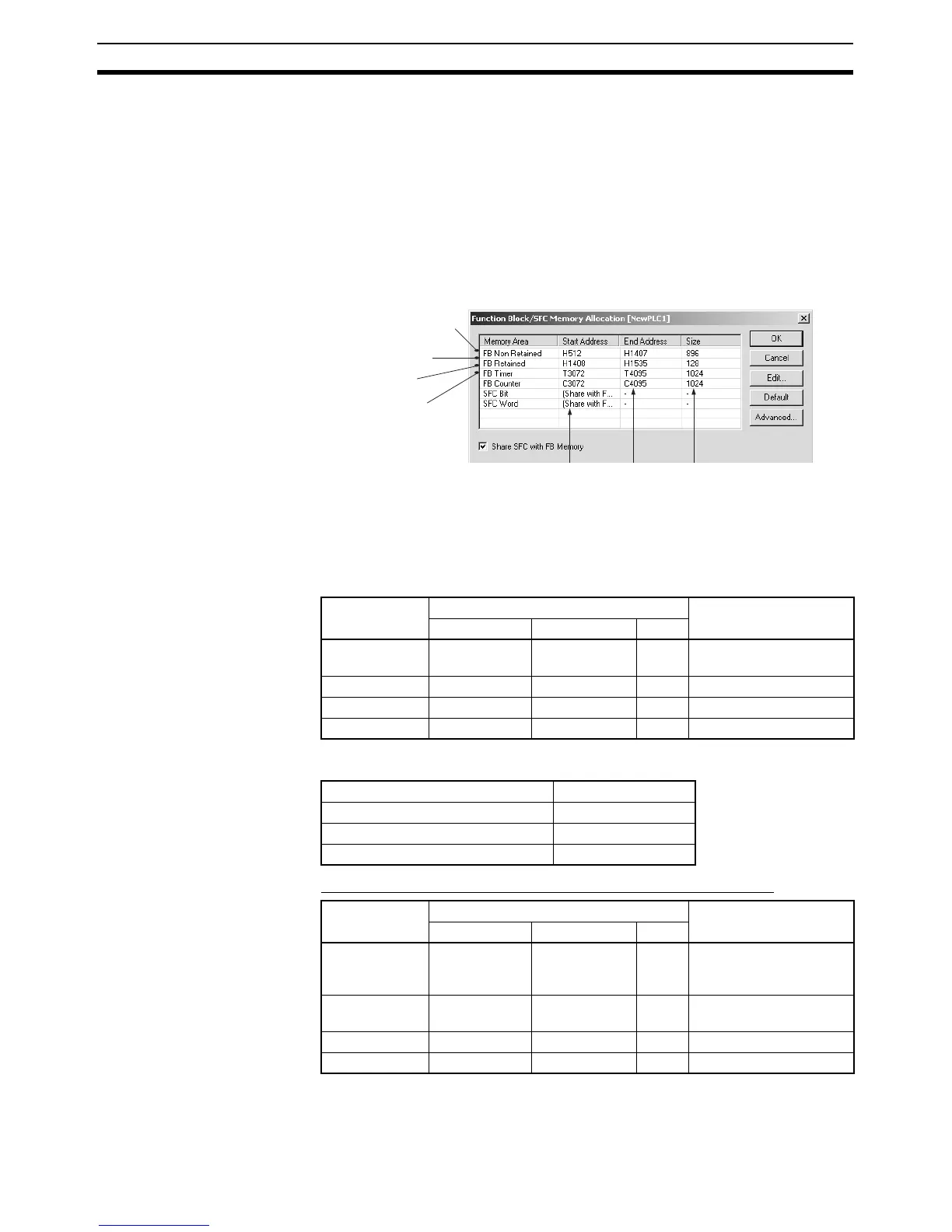
3-2-6 Setting the FB Instance Areas
The areas where addresses for variables used in function blocks are allocated
can be set. These areas are called the function block instance areas.
1,2,3... 1. Select the instance in the Ladder Section Window or in the global symbol
table, and then select Function Block/SFC Memory - Function
Block/SFC Memory Allocation from the PLC Menu.
The Function Block/SFC Memory Allocation Dialog shown below will ap-
pear.
2. Set the FB instance areas.
The non-retained and retained areas are set in words. The timer and
counter areas are set by time and counter numbers.
The default values are as follows:
CJ2-series CPU Units
Note Force-setting/resetting is enabled when the following EM banks are specified:
CS/CJ-series CPU Units Ver. 3.0 or Later, and NSJ Controllers
Note (1) Bit data can be accessed even if the DM or EM Area is specified for the
non-retained area or retained area.
FB Instance
Area
Default value Applicable memory
areas
Start address End address Size
Non Retain H512 H1407 896 CIO, WR, HR, DM,
EM (See note.)
Retain H1408 H1535 128 HR, DM, EM (See note.)
Timers T3072 T4095 1024 TIM
Counters C3072 C4095 1024 CNT
Non-retained area
Retained area
Counter area
Timer area
First
address
Last
address
Size
CJ2H-CPU64(-EIP)/-CPU65(-EIP) EM bank 3
CJ2H-CPU66(-EIP) EM banks 6 to 9
CJ2H-CPU67(-EIP) EM banks 7 to E
CJ2H-CPU68(-EIP) EM banks 11 to 18
FB Instance
Area
Default value Applicable memory
areas
Start address End address Size
Non Retain
(See notes 1
and 3.)
H512 (See
note 2.)
H1407 (See
note 2.)
896 CIO, WR, HR, DM, EM
Retain (See
note 1.)
H1408 (See
note 2.)
H1535 (See
note 2.)
128 HR, DM, EM
Timers T3072 T4095 1024 TIM
Counters C3072 C4095 1024 CNT