330
Appendix
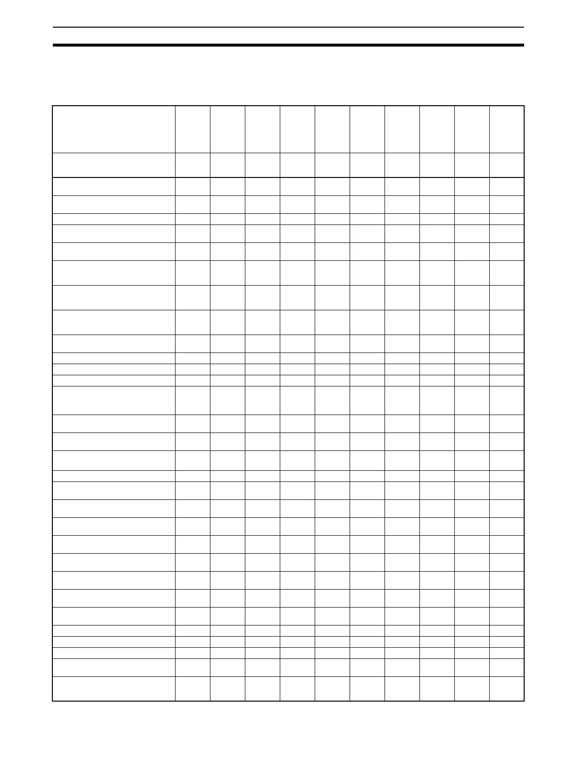
Initialization According to Parameter Changes
The parameters that are initialized when parameters are changed are shown under Related initialized parame-
ters.
Changed
parameter
Related initialized parameters
Input
type
Tempera
ture unit
Scaling
Lower
Limit
Scaling
Upper
Limit
SP
Lower
Limit
SP
Upper
Limit
PID/ON
OFF
Stan-
dard or
Heating/
Cooling
Pro-
gram
Pattern
Valid
Program
Bank
ST Remote
SP
Enable
Related parameter initialization
execution condition
--- Temper-
ature
input
Analog
input
--- Standar
d
models
Stan-
dard
models
--- (See
note 21.)
--- ---
SP Upper Limit, SP Lower Limit ● (See
note 1.)
● (See
note 1.)
● (See
note 1.)
--- --- --- --- --- --- ---
Set Point ● (See
note 3.)
● (See
note 3.)
● (See
note 3.)
● (See
note 3.)
--- --- --- --- --- ---
Bank No. --- --- --- --- --- --- ●●--- ---
RUN/STOP --- --- --- --- --- --- ● (See
note 22.)
--- --- ---
RT ● (See
note 4.)
--- --- --- --- --- --- --- --- ---
Proportional Band (See note 16.) ● (See
notes 4
and 15.)
--- --- --- --- --- --- --- --- ---
Integral Time (See note 16.) ● (See
notes 4
and 15.)
--- --- --- --- --- --- --- --- ---
Derivative Time (See note 16.) ● (See
notes 4
and 15.)
--- --- --- --- --- --- --- --- ---
MV Upper Limit, MV Lower Limit --- --- --- --- --- ● (See
note 6.)
--- --- --- ---
MV at Stop --- --- --- --- --- ● --- --- --- ---
MV at PV Error --- --- --- --- --- ● --- --- --- ---
Manual MV --- --- --- --- --- --- --- --- --- ---
Transfer Output Upper Limit,
Transfer Output Lower Limit
(See note 5.)
● (See
notes 1
and 5.)
● (See
notes 1
and 5.)
● (See
notes 1
and 5.)
● (See
notes 1
and 5.)
--- ● (See
notes 2
and 5.)
--- --- --- ---
SP Mode ● (See
note 19.)
--- --- --- ● (See
note 19.)
● (See
note 19.)
--- --- ● (See
note 12.)
● (See
note 13.)
Remote SP Enable ● (See
note 19.)
--- --- --- ● (See
note 19.)
● (See
note 19.)
--- --- ● (See
note 12.)
---
Remote SP Upper Limit,
Remote SP Lower Limit
● (See
note 2.)
● (See
note 2.)
● (See
note 2.)
● (See
note 2.)
--- --- --- --- --- ---
Control Output 1 Assignment --- --- --- --- --- ● ● --- --- ---
Control Output 2 Assignment --- --- --- --- --- ● (See
note 7.)
● (See
note 7.)
--- --- ---
Auxiliary Output 1 Assignment --- --- --- --- --- ● (See
note 8.)
● (See
note 8.)
--- --- ---
Auxiliary Output 2 Assignment --- --- --- --- --- ● (See
note 7.)
● (See
note 7.)
--- --- ---
Auxiliary Output 3 Assignment --- --- --- --- --- ● (See
note 7.)
● (See
note 7.)
--- --- ---
Event Input Assignment 1 --- --- --- --- --- --- ● (See
note 9.)
--- --- ---
Event Input Assignment 2 --- --- --- --- --- --- ● (See
note 9.)
--- --- ---
Event Input Assignment 3 --- --- --- --- --- --- ● (See
note 9.)
--- --- ---
Event Input Assignment 4 --- --- --- --- --- --- ● (See
note 9.)
--- --- ---
Move to Protect Level --- --- --- --- --- --- --- --- --- ---
MV Display Selection --- --- --- --- --- ● --- --- --- ---
Position Proportional Dead Band --- --- --- --- --- --- --- --- --- ---
Temperature Input Shift ● (See
note 15.)
--- --- --- --- --- --- --- --- ---
Upper Limit Temperature Input Shift
Value, Lower Limit Temperature Input
Shift Value
● (See
note 15.)
--- --- --- --- --- --- --- --- ---

 Loading...


