37
5-2 Wiring
Refer to the terminal arrangements to wire the E5J. Before wiring, observe the
following.
1, 2, 3...
1. When connecting extension wires to the thermocouple, use proper compen-
sating lead wires.
2. When connecting extension wires to the platinum resistance thermometer,
use three low-resistance wires of equal resistance.
3. The power supply must not be influenced by noise. If necessary use a noise
filter.
4. All the wires connected to the input circuitry must be separated from the
wires connected to the power supply or output circuitry.
5. Use shielded wires where static inductance noise is present.
6. Twist the input wires evenly and closely if there is any electromagnetic in-
ductance noise.
5-2-1 Connection
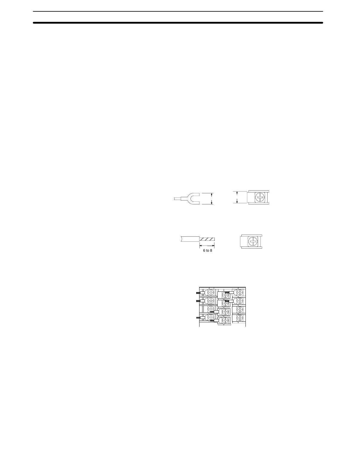
With Solderless Terminals Use solderless terminals for M3.5 screws. The terminal screws are M3.5 x 8 self-
up screws.
7.1 max.
7.3
Solder-dipped Leads It is possible to connect solder-dipped leads to the terminals with ease. The
length of each bare lead wire should be 6 to 8 mm.
6 to 8
For side-by-side mounting, Thermac J-series Temperature Controllers are de-
signed so that all the lead wires can be connected to the terminals in the same
direction.
Wiring
Section 5-2