13
2-3-3 Alarm Mode Setting
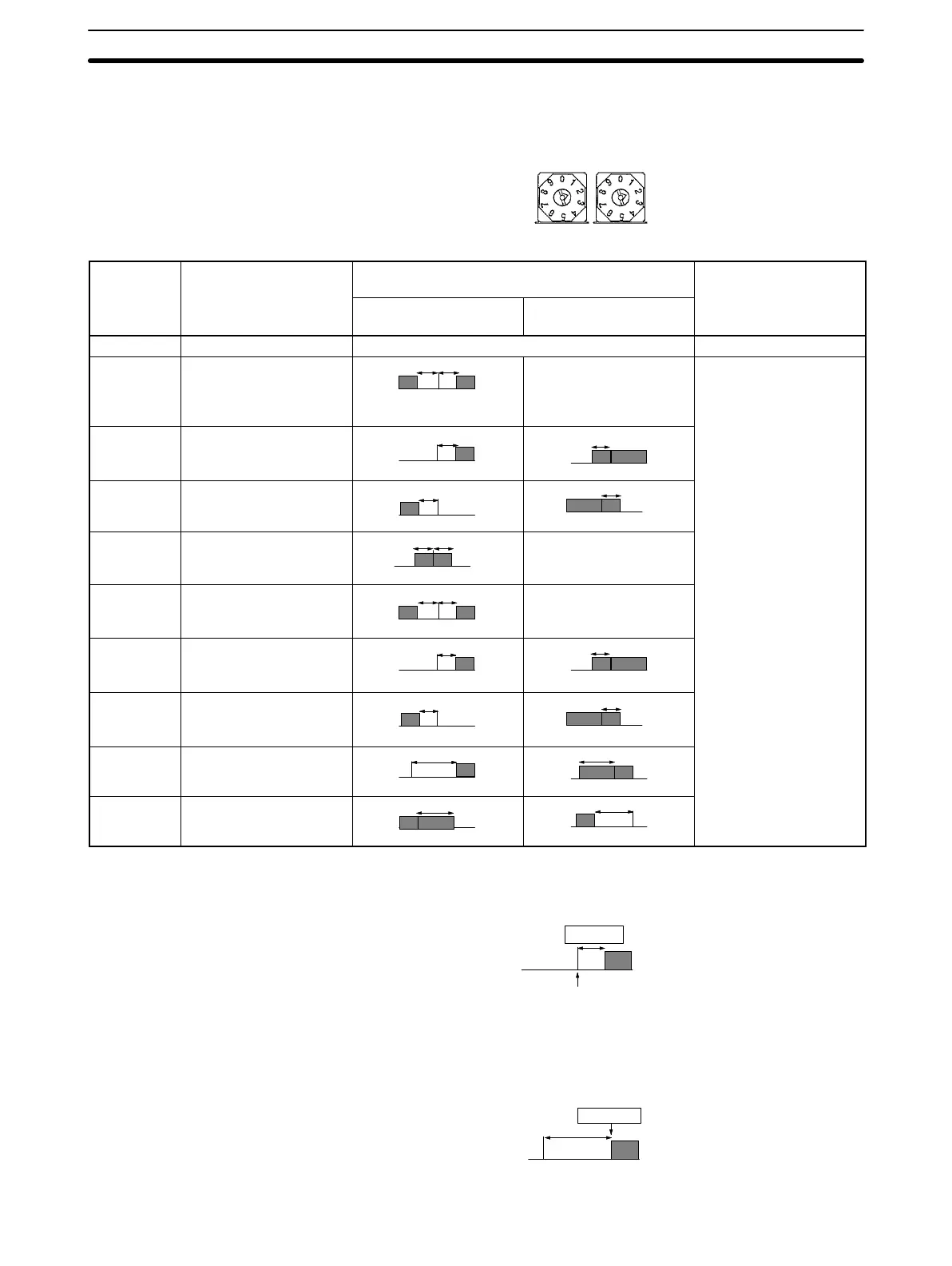
ALM1 and ALM2 are both factory-set to 2 (upper limit alarm). Refer to the follow-
ing table for the selection of the desired alarm mode.
ALM2 ALM1
Selector
no.
Alarm mode Alarm output Setting range
Positive alarm set
value
Negative alarm set
value
0 No alarm function OFF ---
1 Upper and lower limit
alarm (deviation)
X
SP
X
Always ON –1999 to 9999 or –199.9
to 999.9 (the decimal
position varies with the
input type)
2 Upper limit alarm
(deviation)
SP
X
X
SP
3 Lower limit alarm
(deviation)
X
SP
SP
X
4 Upper and lower limit
range alarm (deviation)
X
SP
X
Always OFF
5 Upper and lower limit
alarm with standby
sequence (deviation)
X
SP
X
Always OFF
6 Upper limit alarm with
standby sequence
(deviation)
SP
X
SP
X
7 Lower limit alarm with
standby sequence
(deviation)
X
SP
SP
X
8 Absolute value upper
limit alarm
X
0
X
0
9 Absolute value lower
limit alarm
X
0
X
0
If the alarm mode switch is set to 1 to 7, the alarm value is set with the deviation
width from the set point as shown in the following diagram.
Alarm value
Set point (SP)
100°C/°F
10°C/°F
If the alarm mode switch is set to 8 or 9, the alarm value is set with the absolute
value from 0°C/°F as shown in the following diagram.
Alarm value
110°C/°F
0°C/°F
Internal Switch Settings
Section 2-3